


2-18 Intel® PXA255 Processor Developer’s Manual
System Architecture
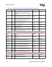
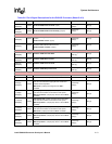
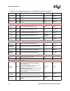
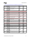
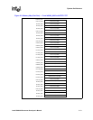
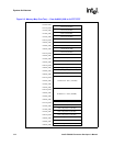
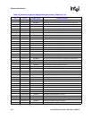
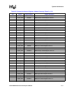
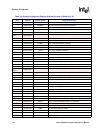
2.12 Memory Map
Figure 2-2 and Figure 2-3 show the full processor memory map.
Any unused register space from 0x4000_0000 to 0x4BFF_FFFF is reserved.
Note: Accessing reserved portions of the memory map will give unpredictable results.
The PCMCIA interface is divided into Socket 0 and Socket 1 space. These two sockets are each
subdivided into I/O, memory and attribute space. Each socket is allocated 256 MB of memory
space.
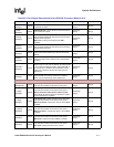
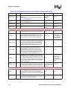
[4]
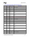
Static Memory Control Pins: During Sleep Mode, these pins can be programmed to either drive the value in the
Sleep State Register or to be placed in Hi-Z. To select the Hi-Z state, software must set the FS bit in the Power
Manager General Configuration Register. If PCFR[FS] is not set, then during the transition to sleep these pins
function as described in [3], above. For nWE, nOE, and nCS[0], if PCFR[FS] is not set, they are driven high by
the Memory Controller before entering sleep. If PCFR[FS] is set, these pins are placed in Hi-Z.
[5]
PCMCIA Control Pins: During Sleep Mode: Can be programmed either to drive the value in the Sleep State
Register or to be placed in Hi-Z. To select the Hi-Z state, software must set PCFR[FP]. If it is not set, then during
the transition to sleep these pins function as described in [3], above.
[6] During sleep, this supply may be driven low. This supply must never be high impedance.
[7] Remains powered in sleep mode.
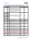
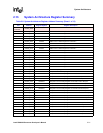
Table 2-7. Pin Description Notes (Sheet 2 of 2)
Note Description