


Intel® PXA255 Processor Developer’s Manual 14-1
Inter-Integrated-Circuit Sound (I
2
S)
Controller 14
I
2
S is a protocol for digital stereo audio. The I
2
S Controller (I2SC) functional block for the
PXA255 processor controls the I
2
S link (I2SLINK), which is a low-power four-pin serial interface
for stereo audio. The I
2
S interface and the Audio CODEC ‘97 (AC’97) interface may not be used at
the same time.
14.1 Overview
The I2SC consists of buffers, status and control registers, serializers, and counters for transferring
digitized audio between the processor system memory and an external I
2
S CODEC.
For playback of digitized audio or production of synthesized audio, the I2SC retrieves digitized
audio samples from processor system memory and sends them to a CODEC through the I2SLINK.
The external digital-to-analog converter in the CODEC then converts the audio samples into an
analog audio waveform.
For recording of digitized audio, the I2SC receives digitized audio samples from a CODEC
(through the I2SLINK) and stores them in processor system memory.
The I
2
S controller supports the normal-I
2
S and the MSB-Justified-I
2
S formats. Four, or optionally
five, pins connect the controller to an external CODEC:
• A bit-rate clock, which can use either an internal or an external source.
• A formatting or “Left/Right” control signal.
• Two serial audio pins, one input and one output.
• The bit-rate clock, an optional system clock also sent to the CODEC by the I2SC.
The I
2
S data can be stored to and retrieved from system memory either by the DMA controller or
by programmed I/O.
For I
2
S systems, additional pins are required to control the external CODEC. Some CODECs use
an L3 control bus, which requires 3 signals — L3_CLK, L3_DATA, and L3_MODE — for writing
bytes into the L3-bus register. The I2SC supports the L3 bus protocol via software control of the
general-purpose I/O (GPIO) pins. The I2SC does not provide hardware control for the L3 bus
protocol.
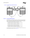
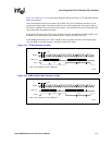
Two similar protocols exist for transmitting digitized stereo audio over a serial path: Normal-I
2
S
and MSB-Justified-I
2
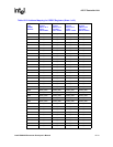
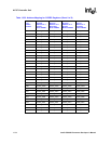
S. Both work with a variety of clock rates, which can be obtained by dividing
the PLL clock by a programmable divider, or from an external clock source. For further details
regarding clock rates, see Table 14-2.