


Intel® PXA255 Processor Developer’s Manual 9-21
I
2
C Bus Interface Unit
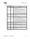
16. Write a 1 to the ISR[IRF] bit to clear the interrupt.
17. Read IDBR data.
18. Clear ICR[STOP] and ICR[ACKNAK] bits
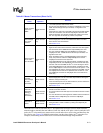
9.6.5 Read 2 Bytes as a Master - Send STOP Using the Abort
1. Load target slave address and R/nW bit in the IDBR. R/nW must be 1 for a read.
2. Initiate the write.
Set ICR[START], clear ICR[STOP], clear ICR[ALDIE], set ICR[TB]
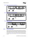
3. When an IDBR Transmit Empty interrupt occurs.
Read ISR: IDBR Transmit Empty (1), Unit busy (1), R/nW bit (1)
4. Write a 1 to the ISR[ITE] bit to clear interrupt.
5. Initiate the read
Clear ICR[START], clear ICR[STOP], set ICR[ALDIE], clear ICR[ACKNAK], set ICR[TB]
6. When an IDBR Receive full interrupt occurs.
Read ISR: IDBR Receive Full (1), Unit Busy (1), R/nW bit (1), ACK/NAK bit (0)
7. Write a 1 to the ISR[IRF] bit to clear the interrupt.
8. Read IDBR data.
9. Clear ICR[STOP] and ICR[ACKNAK] bits
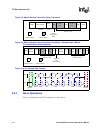
10. Initiate the read.
Clear ICR[START], clear ICR[STOP], set ICR[ALDIE], set ICR[ACKNAK], set ICR[TB]
ICR[STOP] is not set because STOP or repeated start will be decided on the byte read.
11. When an IDBR Receive full interrupt occurs.
Read ISR: IDBR Receive Full (1), Unit Busy (1), R/nW bit (1), ACK/NAK bit (1)
12. Write a 1 to the ISR[IRF] bit to clear the interrupt.
13. Read IDBR data.
14. Initiate STOP abort condition (STOP with no data transfer).
Set ICR[MA]
Note: If a NAK is not sent in Step 11, the next transaction must involve another data byte read.
9.7 Glitch Suppression Logic
The I
2
C unit has built-in glitch suppression logic that suppresses glitches of 60ns or less. This is
within the 50ns glitch suppression specification.
9.8 Reset Conditions
Software must ensure that the I
2
C unit is not busy before it asserts a reset. Software must also
ensure that the I
2
C bus is idle when the unit is enabled after reset. When directed to reset, the I
2
C
unit, except for ISAR, returns to the default reset condition. ISAR is not affected by a reset.