


7-34 Intel® PXA255 Processor Developer’s Manual
LCD Controller
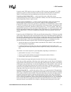
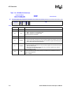
These are read-only registers. Ignore reads from reserved bits.
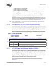
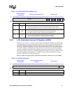
7.6.5.4 LCD DMA Frame ID Registers (FIDRx)
FIDRx, shown in Table 7-9, correspond to DMA channels 0 and 1 and contain an ID field that
describes the current frame. The particular use of this field is up to the user. This ID register is
copied to the LCD Controller Interrupt ID Register when an interrupt occurs.
These read-only registers are loaded indirectly via the frame descriptors, as described in
Section 7.6.5.1.
These are read-only registers. Ignore reads from reserved bits.
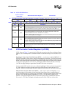
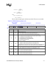
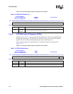
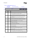
Table 7-8. FSADRx Bit Definitions
Physical Address
channel 0: 0x4400_0204
channel 1: 0x4400_0214
FSADR0
FSADR1
LCD Controller
Bit
31 30 29 28 27 26 25 24 23 22 21 20 19 18 17 16 15 14 13 12 11 10 9 8 7 6 5 4 3 2 1 0
Frame Source Address
Reset
? ? ? ? ? ? ? ? ? ? ? ? ? ? ? ? ? ? ? ? ? ? ? ? ? ? ? ? ? ? ? ?
Bits Name Description
31:0
Frame
Source
Address
Address of the palette or pixel frame data in memory.
Bits [2:0] must be zero for proper memory alignment.
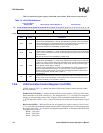
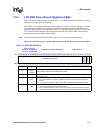
Table 7-9. FIDRx Bit Definitions
Physical Address
channel 0: 0x4400_0208
channel 1: 0x4400_0218
FIDR0
FIDR1
LCD Controller
Bit
31 30 29 28 27 26 25 24 23 22 21 20 19 18 17 16 15 14 13 12 11 10 9 8 7 6 5 4 3 2 1 0
Frame ID
reserved
Reset
? ? ? ? ? ? ? ? ? ? ? ? ? ? ? ? ? ? ? ? ? ? ? ? ? ? ? ? ? X X X
Bits Name Description
31:3 Frame ID Frame ID.
2:0 — reserved