


13-4 Intel® PXA255 Processor Developer’s Manual
AC’97 Controller Unit
The ACUNIT provides synchronization for all data transaction on the AC-link. A data transaction
is made up of 256 bits of information broken up into groups of 13 time slots and is called a frame.
Time slot 0 is called the Tag Phase and is 16 bits long. The other 12 time slots are called the Data
Phase. The Tag Phase contains one bit that identifies a valid frame and 12 bits that identify the time
slots in the Data Phase that contain valid data. Each time slot in the Data Phase is 20 bits long.
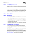
A frame begins when SYNC goes high. The amount of time that SYNC is high corresponds to the
Tag Phase. AC’97 frames occur at fixed 48 kHz intervals and are synchronous to the 12.288 MHz
bit rate clock, BITCLK.
The ACUNIT and the CODEC use the SYNC and BITCLK to determine when to send transmit
data and when to sample receive data. A transmitter transitions the serial data stream on each rising
edge of BITCLK and a receiver samples the serial data stream on each falling edge of BITCLK.
The transmitter must tag the valid slots in its serial data stream. The valid slots are tagged in slot 0.
Serial data on the AC-link is ordered most significant bit (MSB) to least significant bit (LSB). The
Tag Phase’s first bit is bit 15 and the first bit of each slot in Data Phase is bit 19. The last bit in any
slot is bit 0.
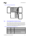
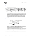
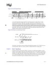
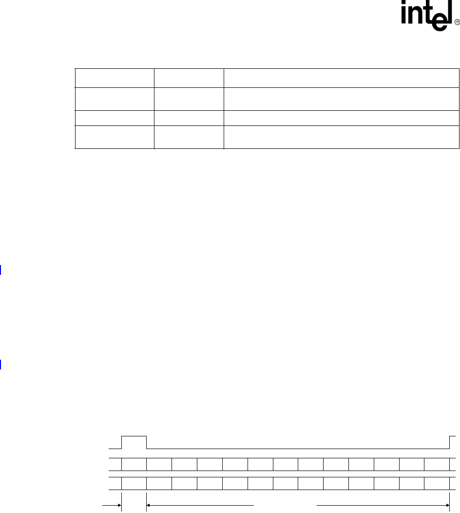
Figure 13-2 shows Tag and Data Phase organization for the ACUNIT and the CODEC. The figure
also lists the slot definitions that the ACUNIT supports.
13.4.1 AC-link Audio Output Frame (SDATA_OUT)
The audio output frame data stream corresponds to the multiplexed bundles that make up the
digital output data that targets the AC’97 DAC inputs and control registers. Each audio output
frame supports up to twelve 20-bit outgoing data time slots. The ACUNIT does not generate
samples larger than 16 bits. The four least significant bits are padded with zeroes.
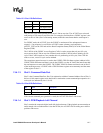
Dedicated
Microphone Input
One input slot
Dedicated microphone input stream in support of stereo AEC and
other voice applications.
I/O Control One output slot One slot dedicated to GPOs on the modem CODEC.
I/O Status One input slot
One slot dedicated to status from GPIs on the modem CODEC.
Data is returned on every frame.
Table 13-2. Supported Data Stream Formats (Sheet 2 of 2)
Channel Slots Comments
Figure 13-2. AC’97 Standard Bidirectional Audio Frame
SYNC
OUTGOING STREAMS
INCOMING STREAMS
TAG
TAG
CMD
ADR
CMD
DATA
PCM
LEFT
PCM
RIGHT
MDM CDC RSRVD RSRVD RSRVD RSRVD I/O control
STATUS
ADR
STATUS
DATA
PCM
LEFT
PCM
RIGHT
MIC
RSRVD RSRVD RSRVD RSRVD RSRVD I/O Status
Slot #
012345
MDM CDC
6 7 8 9 10 11 12
Data PhaseTag Phase
RSRVDRSRVD