


4-20 Intel® PXA255 Processor Developer’s Manual
System Integration Unit
• GPIO[1] is an input configured to alternate function 1 (ALT_FN_1_IN)
• GPIO[5:2] are reserved and configured as normal GPIOs inputs
• GPIO[12:6] are outputs configured to alternate function 1 (ALT_FN_1_OUT)
• GPIO[13] is an output configured to alternate function 2 (ALT_FN_2_OUT)
• GPIO[14] is an input configured to alternate function 1 (ALT_FN_1_IN)
• GPIO[15] is an output configured to alternate function 2 (ALT_FN_2_OUT)
This programming sequence is required for programming the GPIO alternate functions out of reset:
1. WRITE GPSR0 0x0000_8000 – this sets GPIO15 (active low chip select) when it is configured
as an output.
2. WRITE GPDR0 0x0000_BFC0
– GPIO[12:6], GPIO[13] and GPIO[15] as outputs. This drives
GPIO[15] high until the alternate function information is programmed. This is required for active
low outputs.
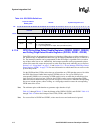
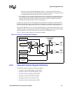
3. WRITE GAFR0_L 0x9955_5004 – this maps the alternate functions of GPIO[15:0]
For GPIOs that need to be configured as outputs, you must first program the GPSR and GPCR
signals so the pin direction is changed. Change pin direction by setting the bit in the GPDR
register—a ‘0’ is driven for active high signals and ‘1’ for active low signals.
Note: For more information on alternate functions, refer to the Source Unit column in Table 4-1 for the
appropriate section of this document.
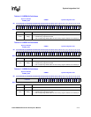
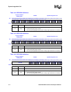
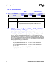
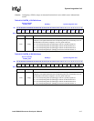
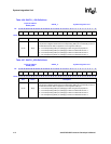
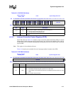
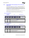
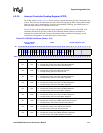
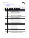
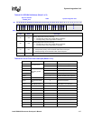
Table 4-24 through Table 4-29 show the bitmaps of the GPIO Alternate Function registers.
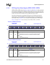
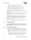
4.2 Interrupt Controller
The Interrupt Controller controls the interrupt sources available to the processor and also contains
the location to determine the first level source of all interrupts. It also determines whether
interrupts cause an IRQ or an FIQ to occur and masks the interrupts. The interrupt controller only
supports a single priority level, however, interrupts can be routed to either IRQs or FIQ, with FIQs
having priority over IRQs.
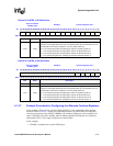
4.2.1 Interrupt Controller Operation
The interrupt controller provides masking capability for all interrupt sources and generates either
an FIQ or IRQ processor interrupt. The interrupt hierarchy of the processor is a two-level structure.
• The first level identifies the interrupts from all the enabled and unmasked interrupt sources in
the Interrupt Controller Mask Register (ICMR). First level interrupts are controlled by these
registers:
— Interrupt Controller Pending Register (ICPR)
– identifies all the active interrupts within
the system
— Interrupt Controller IRQ Pending Register (ICIP)
– contains the interrupts from all
sources that can generate an IRQ interrupt. The Interrupt Controller Level Register
(ICLR) is programmed to send interrupts to the ICIP to generate an IRQ.