


9-24 Intel® PXA255 Processor Developer’s Manual
I
2
C Bus Interface Unit
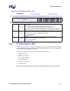
10 BEIE
Bus Error Interrupt Enable:
0 = Disable interrupt.
1 = Enables the I
2
C unit to interrupt the processor for the following I
2
C bus errors:
• As a master transmitter, no ACK was detected after a byte was sent.
• As a slave receiver, the I
2
C unit generated a NAK pulse.
NOTE: Software is responsible for guaranteeing that misplaced START and STOP
conditions do not occur. See Section 9.7.
9IRFIE
IDBR Receive Full Interrupt Enable:
0 = Disable interrupt.
1 = Enables the I
2
C unit to interrupt the processor when the IDBR receives a data byte
from the I
2
C bus.
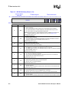
8ITEIE
IDBR Transmit Empty Interrupt Enable:
0 = Disable interrupt.
1 = Enables the I
2
C unit to interrupt the processor after transmitting a byte onto the I
2
C
bus.
7GCD
General Call Disable:
0 = Enables the I
2
C unit to respond to general call messages.
1 = Disables I
2
C unit response to general call messages as a slave.
Must be set when the I
2
C unit sends a master mode general call message.
6IUE
I
2
C Unit Enable:
0 = Disables the unit and does not master any transactions or respond to any slave
transactions.
1 = Enables the I
2
C unit (defaults to slave-receive mode).
Software must ensure that the I
2
C bus is idle before it sets this bit.
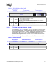
5SCLE
SCL Enable:
0 = Disables the I
2
C unit from driving the SCL line.
1 = Enables the I
2
C clock output for master mode operation.
4MA
Master Abort: generates a STOP without transmitting another data byte when the I
2
C unit
is in master mode.
0 = The I
2
C unit transmits STOP using the STOP ICR bit only.
1 = The I
2
C unit sends STOP without data transmission.
In master-transmit mode, after a data byte is sent, the ICR’s Transfer Byte bit is cleared and
IDBR Transmit Empty bit is set. When no more data bytes need to be sent, setting master
abort bit sends the STOP. The Transfer Byte bit (03) must remain clear.
In master-receive mode, when a NAK is sent without a STOP (STOP ICR bit was not set)
and the processor does not send a repeated START, setting this bit sends the STOP. Once
again, the Transfer Byte bit (03) must remain clear.
3TB
Transfer Byte: used to send/receive a byte on the I
2
C bus.
0 = Cleared by I
2
C unit when the byte is sent/received.
1 = Send/receive a byte.
The processor can monitor this bit to determine when the byte transfer is completed. In
master or slave mode, after each byte transfer, including ACK/NAK bit, the I
2
C unit holds
the SCL line low (inserting wait states) until the Transfer Byte bit is set.
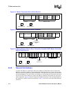
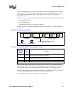
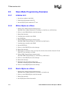
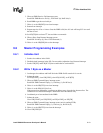
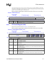
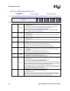
Table 9-10. ICR Bit Definitions (Sheet 2 of 3)
Physical Address
4030_1690
I
2
C Control Register I
2
C Bus Interface Unit
Bit
31 30 29 28 27 26 25 24 23 22 21 20 19 18 17 16 15 14 13 12 11 10 9 8 7 6 5 4 3 2 1 0
reserved
FM
UR
SADIE
ALDIE
SSDIE
BEIE
IRFIE
ITEIE
GCD
IUE
SCLE
MA
TB
ACKNAK
STOP
START
Reset 0 0 0 0 0 0 0 0 0 0 0 0 0 0 0 0 0 0 0 0 0 0 0 0 0 0 0 0 0 0 0