


10-20 Intel® PXA255 Processor Developer’s Manual
UARTs
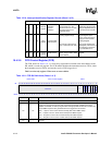
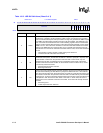
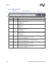
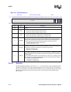
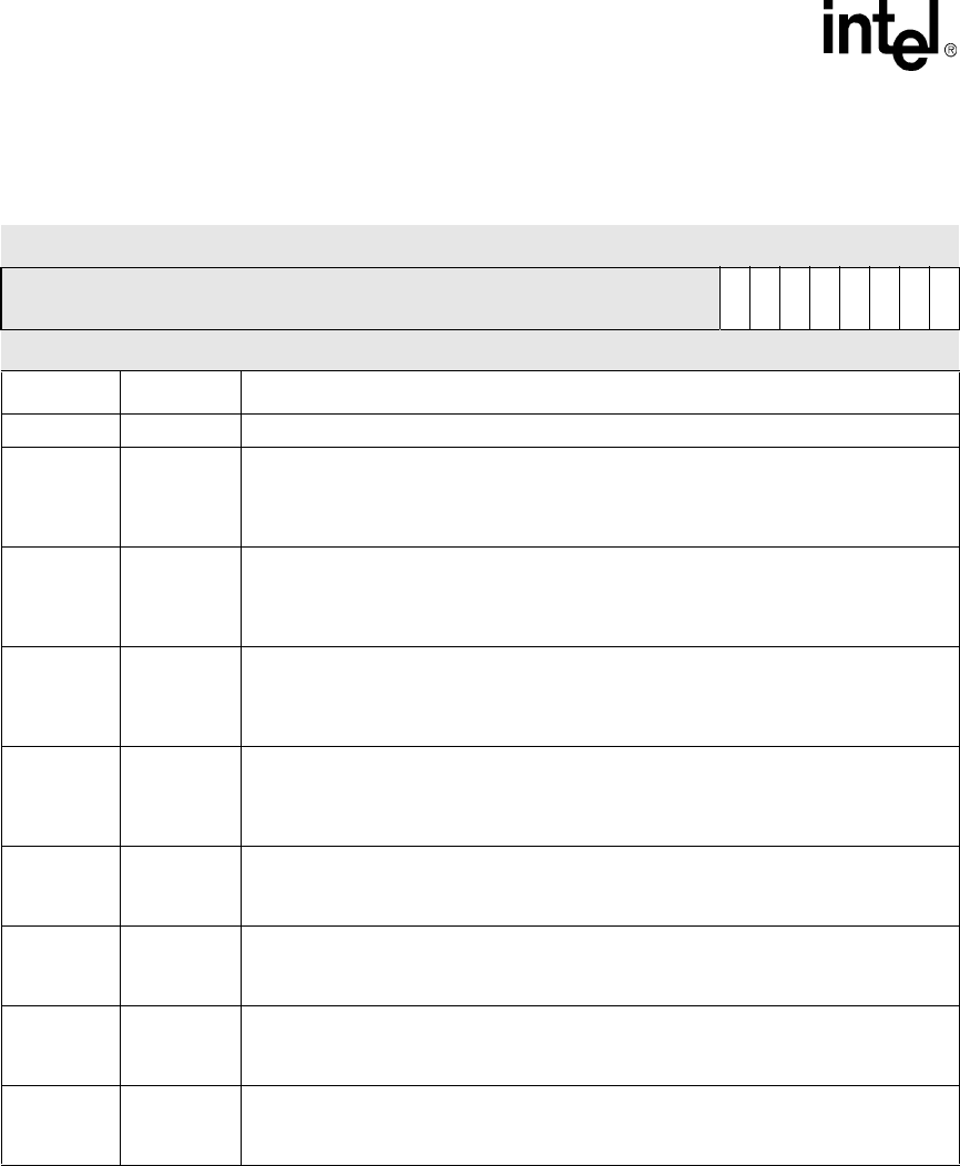
Table 10-15. MSR Bit Definitions
Base+0x18 Modem Status Register UART
Bit
31 30 29 28 27 26 25 24 23 22 21 20 19 18 17 16 15 14 13 12 11 10 9 8 7 6 5 4 3 2 1 0
reserved
DCD
RI
DSR
CTS
DDCD
TERI
DDSR
DCTS
Reset 0 0 0 0 0 0 0 0 0 0 0 0 0 0 0 0 0 0 0 0 0 0 0 0 0 0 0 0 0 0 0 0
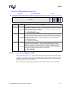
Bits Name Description
31:8 — reserved
7DCD
Data Carrier Detect: Complement of the Data Carrier Detect (nDCD) input. Equivalent to
MCR[OUT2] if MCR[LOOP] is set.
0 – nDCD pin is 1
1 – nDCD pin is 0
6RI
Ring Indicator: Complement of the Ring Indicator (nRI) input. Equivalent to MCR[OUT1] if
MCR[LOOP] is set.
0 – nRI pin is 1
1 – nRI pin is 0
5DSR
Data Set Ready: Complement of the Data Set Ready (nDSR) input. Equivalent to
MCR[DTR] if MCR[LOOP] is set.
0 – nDSR pin is 1
1 – nDSR pin is 0
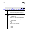
4CTS
Clear To Send: Complement of the Clear to Send (nCTS) input. Equivalent to MCR[RTS] if
MCR[LOOP] is set.
0 – nCTS pin is 1
1 – nCTS pin is 0
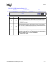
3DDCD
Delta Data Carrier Detect:
0 – No change in nDCD pin since last read of MSR
1 – nDCD pin has changed state
2TERI
Trailing Edge Ring Indicator:
0 – nRI pin has not changed from 0 to 1 since last read of MSR
1 – nRI pin has changed from 0 to 1
1DDSR
Delta Data Set Ready:
0 – No change in nDSR pin since last read of MSR
1 – nDSR pin has changed state
0 DCTS
Delta Clear To Send:
0 – No change in nCTS pin since last read of MSR
1 – nCTS pin has changed state