


Chapter 5-Cascading Conferences
Polycom, Inc. 5-9
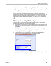
At this point the Conference A organizer or any other participant in the conference can enter
the required information for the IVR session using DTMF codes. For example, the meeting
organizer enters the destination conference ID - 12345.
Any DTMF input from conference A is forwarded to the Entry Queue on MCU B to
complete the IVR session and enable the move of the participant to the destination
conference B.
Once the DTMF codes are entered and the IVR session is completed, the participant is
connected to the conference and the connection between the conferences is established. The
system automatically identifies the calling participant as an MCU and the connection is
identified as a cascading link and the cascading link icon is displayed for the participant
().
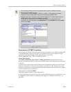
RMX Configuration Enabling ISDN Cascading Links
To enable Gateway-to-Gateway, Gateway-to-MCU and MCU-to-MCU calls over ISDN
Cascading links, the following configurations are required:
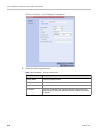
• Modifying the IP Network Service to include the MCU Prefix in the Gatekeeper (in the
Gatekeepers dialog box). For more details, see "Modifying the Default IP Network Service”
on page 16-11.
• ISDN Network Service is configured in both MCUs. For more details, "Modifying an
ISDN/PSTN Network Service” on page 16-47.
• Configuring a Gateway Profile and assigning dial-in ISDN/PSTN numbers. For details,
see "Defining the Gateway Profile” on page 19-18.
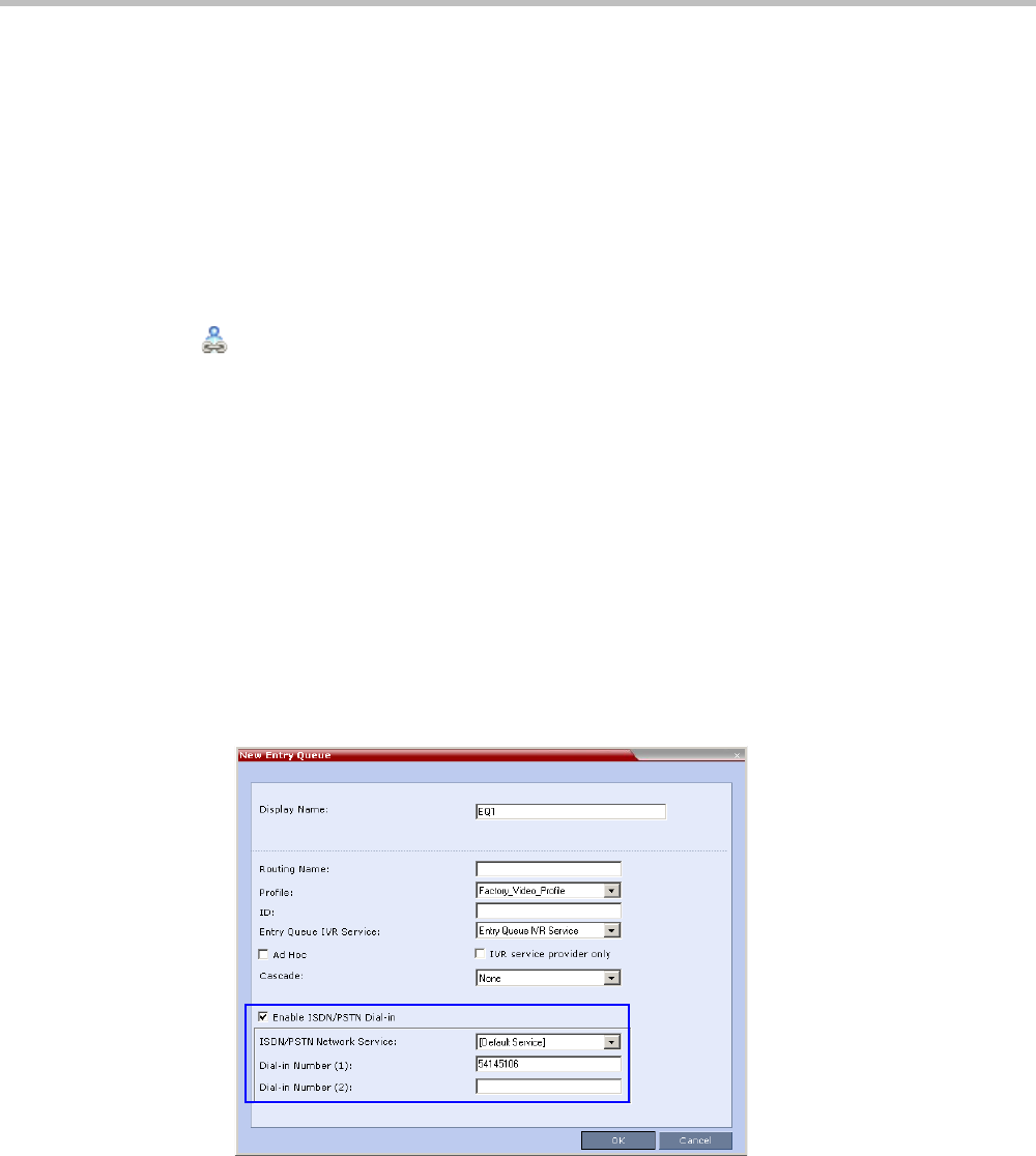
• Configure the Entry Queue or conference (for direct dial-in) is enabled for ISDN
connection and a dial-in number is assigned (for example 54145106).
• Defining the dial-in ISDN participant in MCU B and Dial-out ISDN participant in MCU
A (for MCU-to-MCU cascading conferences).