


1. OVERVIEW
1 - 11
MELSEC
GOT
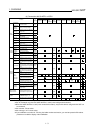
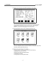
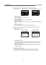
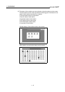
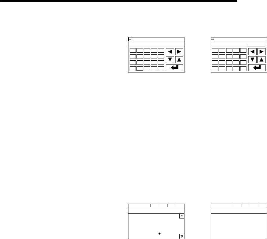
(2) Data can be changed by test operation (see Section 9.6 for details).
(Test sample) When M0 is on
NETWK No.[ 0] STATION[FF] DEC
DEVICE[ M] [ 0] RST:0 SET:1[1]
7
4
1
0
8
5
2
−
9
6
3
A
C
E
AC
B
D
F
DEL
!
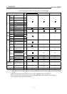
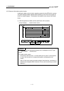
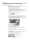
When changing D0 present value
NETWK No.[ 0] STATION[FF] DEC
DEVICE[ D] [ 0] VL[
K-2147483648
]
7
4
1
0
8
5
2
−
6
3
A
C
E
AC
B
D
F
DEL
!
9
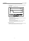
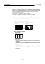
1) Test for bit device
Device specified by user is turned on or off.
2) Test for word device
Writes designated value into device specified by user.
3) Test for timer/counter
Writes in designated value as current value or set values of device specified by
user.
4) Test for buffer memory
Writes designated value into buffer memory specified by user.
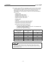
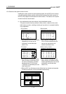
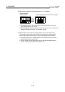
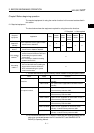
(3) Display format can be changed and device comments can be displayed (see
Section 9.1.2 for details).
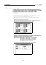
(Sample display) For entry monitor
(comment display)
D 200 30
[Line 1 current units ]
W 200 43
[Production line A ]
R 50 68378428 DW
[link status ]
X 3
[Input switch 3 ]
NETWKNo.[ 0] STATION[FF]
DEVICE MONITOR
TEST MENU FORM SET
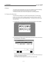
For batch monitor
(hexadecimal display)
D 10 H 7FFF D 18 H FE0C
D 11 H 0000 D 19 H 0CA2
D 12 H 0000 D 20 H 0000
D 13 H FFFF D 21 H 0000
D 14 H 0000 D 22 H 0000
D 15 H 0003 D 23 H 8000
D 16 H 0000 D 24 H 0000
D 17 H 0000 D 25 H 0000
NETWK No.[ 0] STATION[FF]
BATCHMONITOR TEST MENU FORM SET
1) Changing display format
The word device values for the entry monitor, batch monitor, T/C monitor, and
the buffer memory monitor are monitored in decimal or hexadecimal format.
2) Device comment display
When the PLC CPU device is monitored, the comments written into the PLC
CPU are displayed.
(4) Other stations can be monitored.
Other stations in data link systems, network systems or CC-Link systems,
including the GOT (or stations connected to the GOT), can be monitored.