


12. OPERATION OF EACH SPECIAL MODULE MONITOR SCREEN
12 - 21
MELSEC
GOT
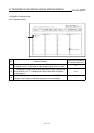
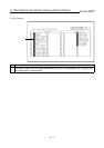
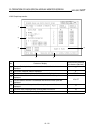
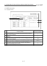
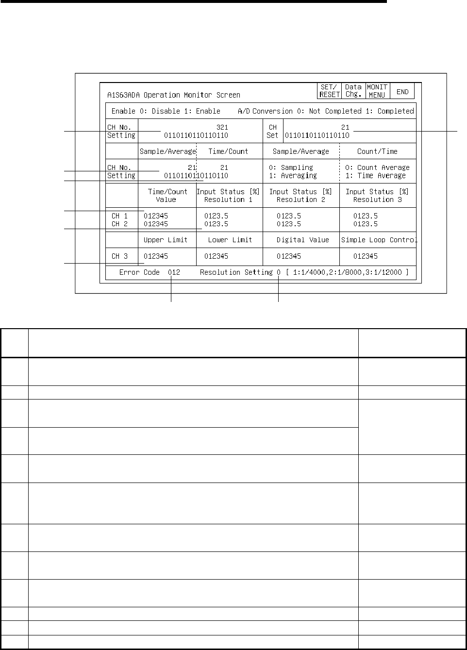
12.9 A1S63DA module monitor
12.9.1 Operation monitor
7)
2)
6)
5)
4)
3)
1)
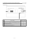
11) 12)
8) 9) 10)
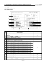
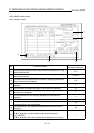
No. Contents of display
Buffer memory address
to reference (decimal)
1)
The specified conversion enabled/disabled status for each channel is
displayed.
0
2) The Conversion Completed flag status for channels 1 and 2 is displayed. 15
3)
The specified status for the averaging processing/sampling processing of
channels 1 and 2 is displayed.
4)
The specified status for the averaging processing of channels 1 and 2 is
displayed.
1
5)
The values set for the time and number of times for averaging processing of
channels 1 and 2 is displayed.
2, 3
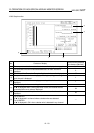
6)
The current output value, a value between 0 to 4000 for the digital output
value of channels 1 and 2, is displayed as a percentage ranging from 0 to
100%. (Resolution selection: 2: 0 to 8000, 3: 0 to 12000)
11, 12
7)
The upper limit of the digital value following D/A conversion with channel 3 is
displayed.
4
8)
The lower limit of the digital value following D/A conversion with channel 3 is
displayed.
5
9)
The set value of the digital value following D/A conversion with channel 3 is
displayed.
10
10) The digital value of channel 3 calculated by simple loop control is displayed. 13
11) The error code is displayed when a writing data error occurs. 16
12) The set resolution selection is displayed. 14