12. OPERATION OF EACH SPECIAL MODULE MONITOR SCREEN
12 - 50
MELSEC
GOT
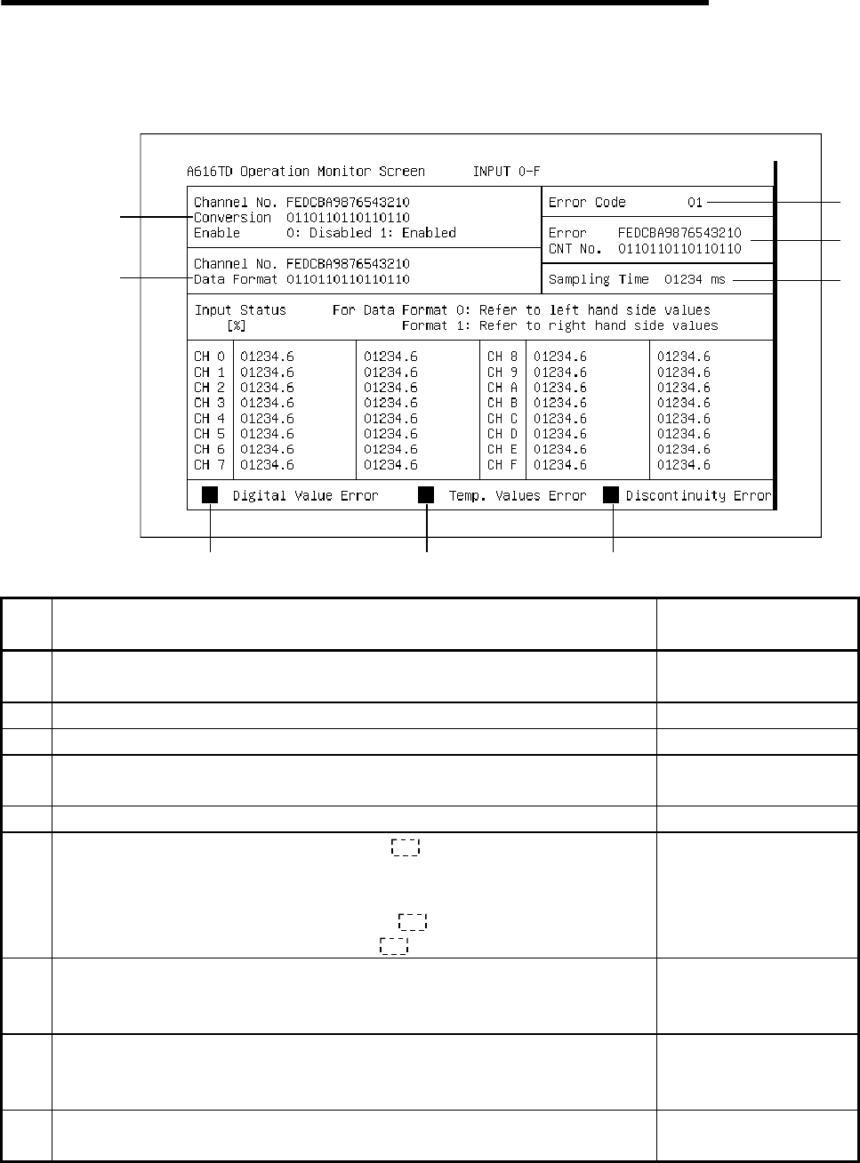
12.18 A616TD module monitor
12.18.1 Operation monitor (INPUT 0-F)
1)
7
)
4)
5)
9
)
2
)
8
)
6) 6)
3)
No. Contents of display
Buffer memory address to
reference (hexadecimal)
1)
The specified D/A conversion enabled/disabled status for each channel is
displayed.
F
2) The set status of the data format for each channel is displayed. 0
3) An error code is displayed when an error occurs. 1
4)
"1" is displayed for CNT No. when an error with error code 01 to 04 has
occurred due to a malfunction of the A60MXT unit or a setting error.
2
5) "0" is displayed for the sampling period current value. 4
6)
For a channel not connected to the A60MX , the current output value, a
value between 0 to 4000 for the digital output of that channel, is displayed as
a percentage ranging from 0 to 100%.
When a channel is connected to the A60MX , the above is displayed for
the digital output value for CH0 of A60MX .
70 to 7F
7)
When the A60MXT is used, "
!
" is displayed when a temperature was input
that exceeds the temperature range set according to the digital output value
set for each channel.
8)
When the A60MXT is used, "
!
" is displayed when a temperature was input
that exceeds the measurement temperature range set for the measurement
range of each channel.
9)
When the A60MXT is used, "
!
" is displayed when broken wire is detected in
the thermocouple or the compensating lead wire.


