12. OPERATION OF EACH SPECIAL MODULE MONITOR SCREEN
12 - 8
MELSEC
GOT
12.2 A61LS module monitor
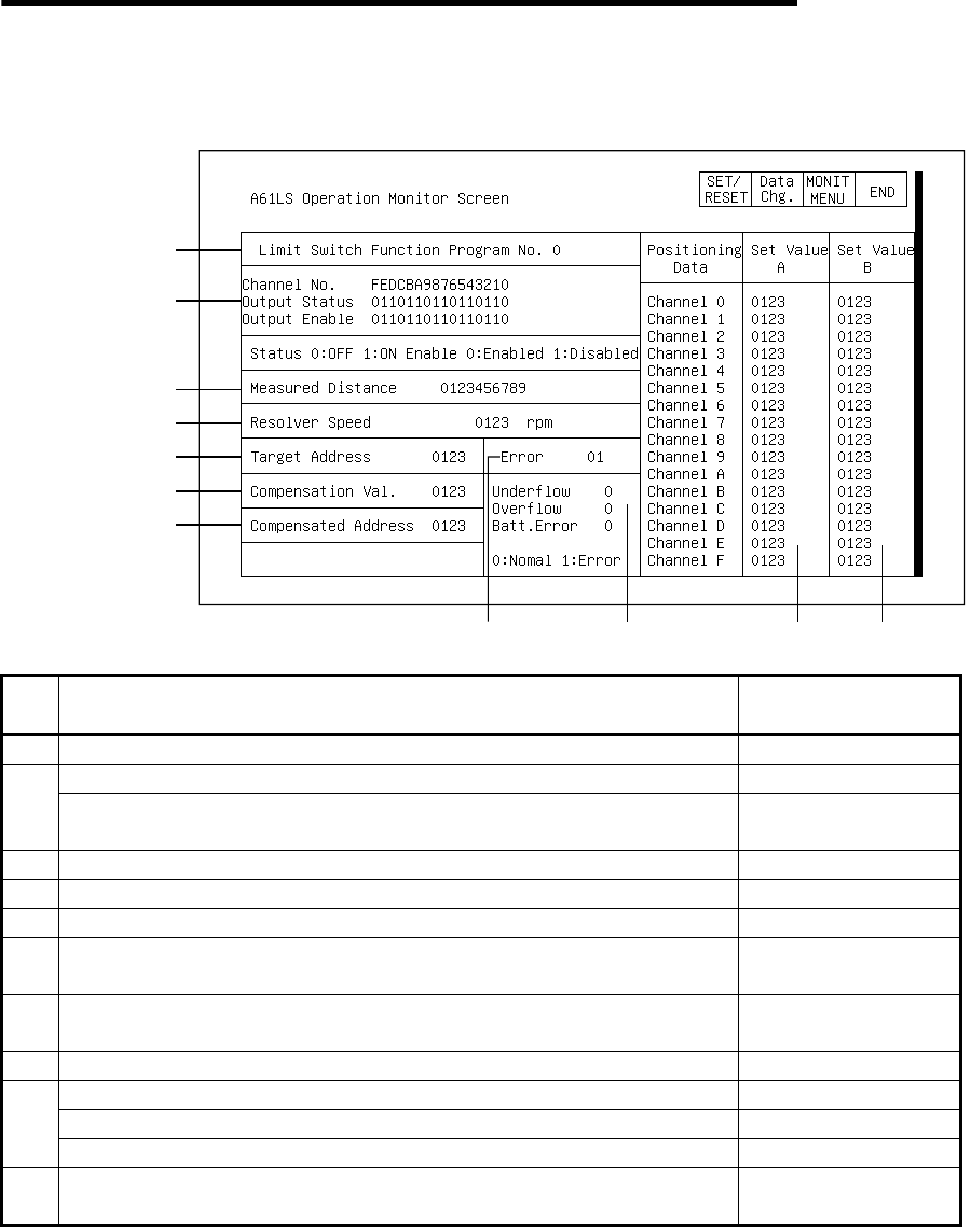
12.2.1 Operation monitor
1)
2)
3)
4)
5)
6)
7)
8)
9) 10) 10)
No. Contents of display
Buffer memory address
to reference (decimal)
1) The number of the program being used is displayed. 11
The output status of each channel is displayed. 4
2)
The specified status for the Output Enable command of each channel is
displayed.
10
3) The measured distance value for the distance detection function is displayed. 5, 6
4) The rotation speed of the resolver connected to A61LS is displayed. 3
5) The set value of the target address for the positioning function is displayed. 12
6)
The compensation value for the zero point compensation function is
displayed.
7
7)
The current value of the resolver after compensation by the zero point
compensation function is displayed.
0
8) The error code is displayed when an error occurs. 8
When an A61LS resolver underflow is detected, "1" is displayed. 2
When an A61LS resolver overflows is detected, "1" is displayed. 19)
When a low battery charge is detected, "1" is displayed. 9
10)
The set values A and B for executing the positioning function are displayed
for each channel.
13 to 44


