12. OPERATION OF EACH SPECIAL MODULE MONITOR SCREEN
12 - 57
MELSEC
GOT
12.19 AD70, A1SD70 module monitor
The contents displayed on each monitor of the AD70 module and A1SD70 module
are nearly identical, except for the sections displaying the module format.
The AD70 module monitor screen is used as an example in each of the following
sections.
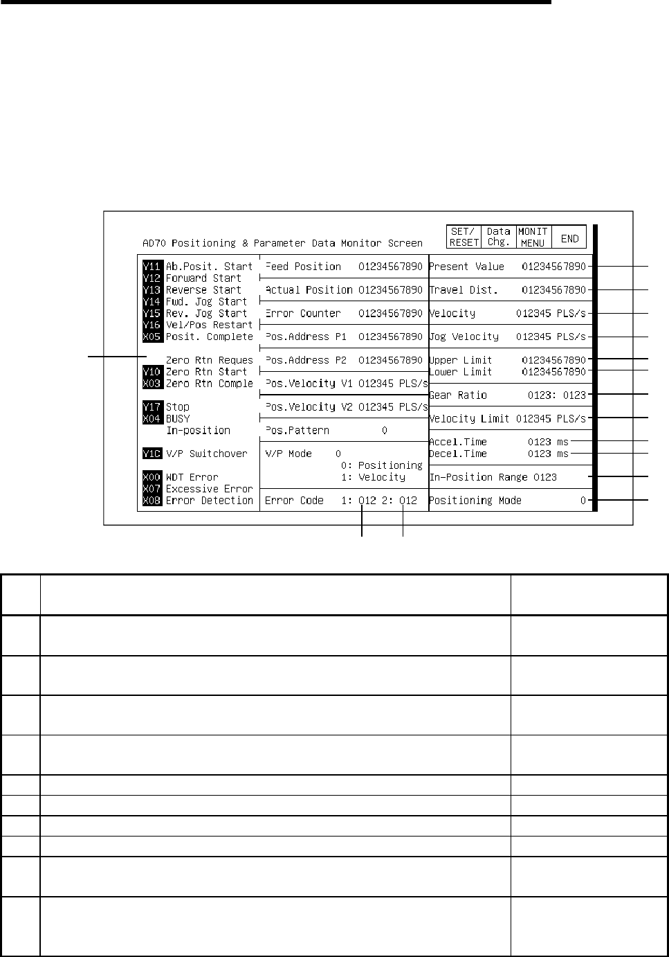
12.19.1 Positioning and parameter data monitor
2)
1)
11)
13)
16)
15)
14)
3)
4)
5)
6)
7)
8)
9)
12)
10)
17)
18)
19)
20)
21)
22)
23)
24)
No. Contents of display
Buffer memory address
to reference (decimal)
1)
The ON/OFF status of the I/O signal corresponding to the PLC CPU is
displayed. The I/O signal is ON when displayed in a reverse display.
2)
The calculated command pulse number (PLS) based on the command value
is displayed.
100, 101
3)
The actual amount of servo movement (feedback pulse number) (PLS)
calculated from the feedback pulse is displayed.
102, 103
4)
The difference between the command pulse number x CMS/CDV and the
feedback pulse number (PLS) is displayed.
106, 107
5) The set value of positioning address P1 (PLS) is displayed. 61, 62
6) The set value of positioning address P2 (PLS) is displayed. 65, 66
7) The set value of positioning velocity V1 is displayed. 63, 64
8) The set value of positioning velocity V2 is displayed. 67, 68
9)
The set status of the positioning pattern is displayed.
0: Positioning 1: 2-speed trapezoid positioning
60
10)
The status of the control mode when changing modes from velocity to
position control is displayed.
0: Positioning control in progress 1: Velocity control in progress
111


