12. OPERATION OF EACH SPECIAL MODULE MONITOR SCREEN
12 - 65
MELSEC
GOT
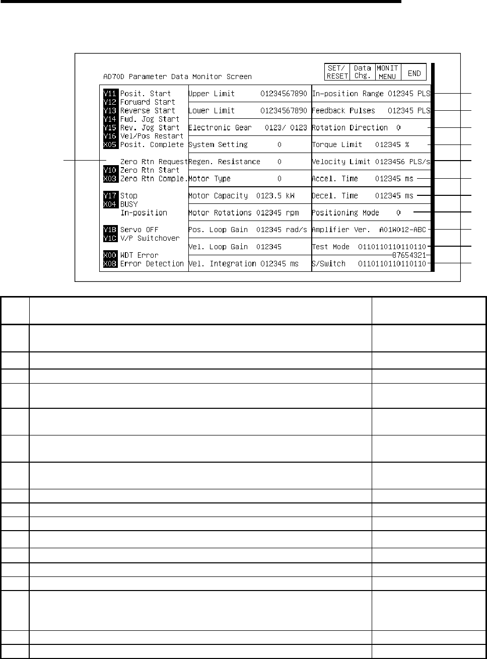
12.20.3 Parameter data monitor
1)
15)
18)
17)
16)
19)
20)
21)
22)
23)
8)
9)
10)
11)
12)
2)
3)
4)
5)
6)
7)
13)
14)
No. Contents of display
Buffer memory address to
reference (decimal)
1)
The ON/OFF status of the I/O signal corresponding to the PLC CPU is displayed. The
I/O signal is on when displayed in a reverse display.
2) The set value (PLS) of the upper stroke limit is displayed. 0, 1
3) The set value (PLS) of the lower stroke limit is displayed. 2, 3
4) The command pulse ratio numerator (CMX) and denominator (CDV) are displayed. 4, 5
5)
The set status of the system is displayed.
0: MR-SB (standard) 1: MR-SB (absolute values)
10
6)
The set status of the regeneration resistance is displayed.
0: None 1: RB30 2: RB50,51 3: RB100, 101
11
7)
The set status of the motor type is displayed.
0: Standard 1: Low inertia L 2: Flat U
12
8) The motor output capacity is displayed. 13
9) The set status of the motor rpm is displayed. 14
10) The set value of the position loop gain is displayed. 15
11) The set value of the velocity loop gain is displayed. 16
12) The set value of the velocity integration is displayed. 17
13) The set value of the in-position range is displayed. 18
14) The feedback pulse number (PLS) of one revolution of the motor is displayed. 19
15)
The set status of the direction of rotation is displayed.
0: Counter-clockwise with address increase
1: Clockwise with address increase
20
16) The set value of the torque limit is displayed. 21
17) The set value of the velocity limit is displayed. 40, 41


