12. OPERATION OF EACH SPECIAL MODULE MONITOR SCREEN
12 - 16
MELSEC
GOT
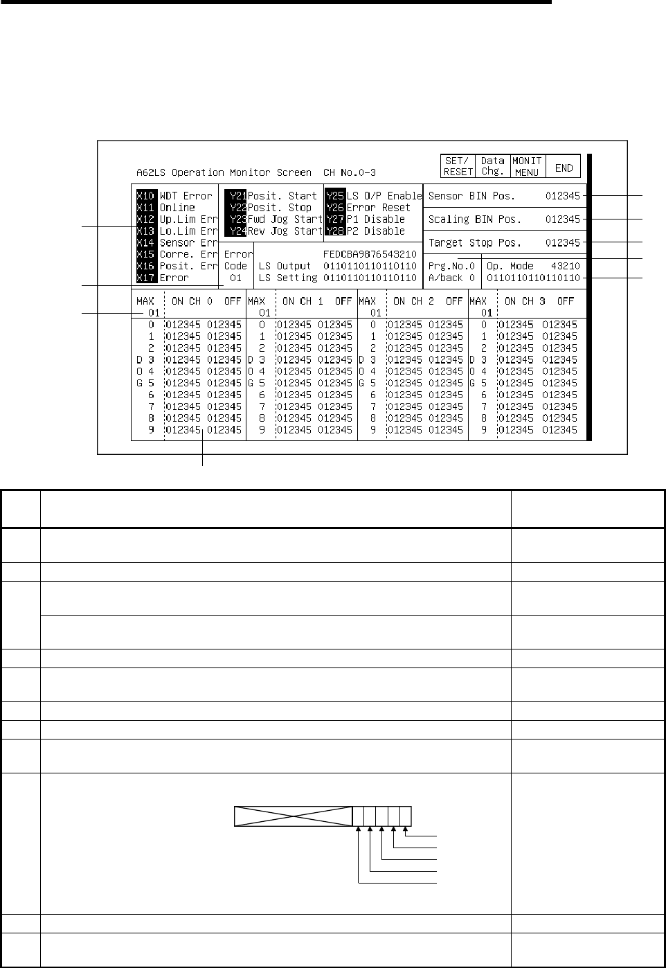
12.7 A62LS module monitor
12.7.1 Operation monitor
As a screen example, we will store the monitor screens from CH. 0 to CH. 3 in the
memory.
1)
2)
10)
11
)
4)
5)
6)
7) 8
)
9)
3)
No.
Contents of display
Buffer memory address
to reference (decimal)
1)
The ON/OFF status of the I/O signal corresponding to the PLC CPU is displayed. The
I/O signal is ON when displayed in a reverse display.
2)
The error code is displayed when an error occurs.
7
The output status of each channel is displayed.
0: OFF 1: ON
4
3)
The set limit switch output enable/disable status for each channel is displayed.
0: Enable 1: Disable
8
4)
The sensor binary current value is displayed.
2, 3
5)
After module conversion of the sensor binary current value to mm or inches, the value
added to the minimum current value is displayed as the scaling binary current value.
0, 1
6)
The set value of the positioning object stop position is displayed.
10, 11
7)
The program number used with the limit switch output function is displayed.
9
8)
The answer back program number corresponding to the program number used with
the limit switch output function is displayed.
5
9)
The A62LS operation mode status is displayed.
b1b2b3b4 b0
Run
Trial run
Set
Parameter
Initial settings
6
10)
The number of multi-dogs that are set is displayed.
12 to 226
11)
The set value for the on position and off position of the multi-dog No. is displayed for
each channel.
12 to 226
"1" is displayed in the bit corresponding to
the selected operation mode.


