9. OPERATION OF THE VARIOUS SYSTEM MONITOR SCREENS
9 - 17
MELSEC
GOT
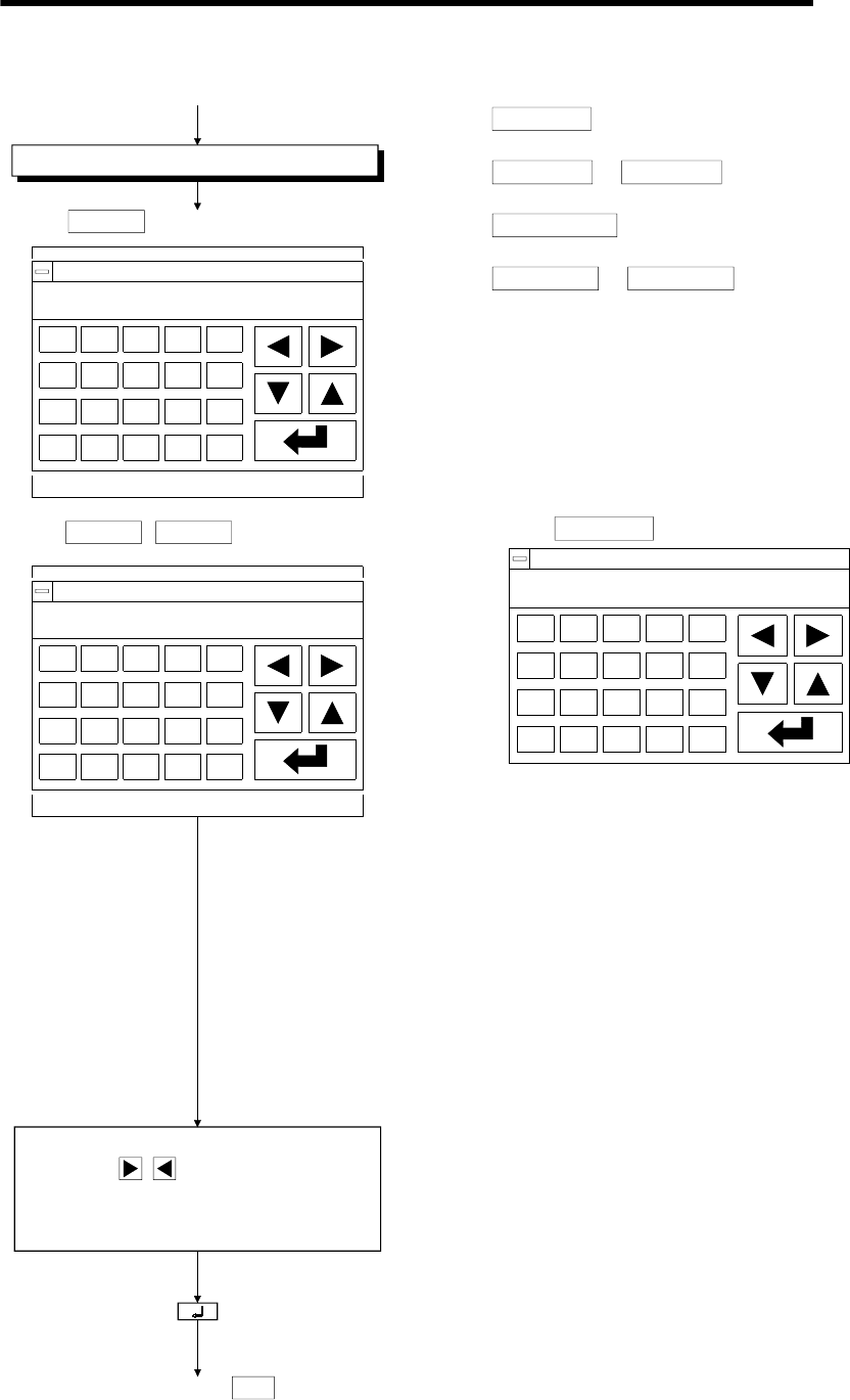
Select test item.
1)
When
SET/RST
is selected.
NETWK No.[ ] STATION[ ]
DEVICE[ ] [ ] RST:0 SET:1
X
B
Y
F
G
ML
AC
S
DEL
NETWK No.[ ] STATION[ ]
DEVICE[ ] [ ] VL[K ]
WD
G
AC
S
DEL
R
CTVZA
E
When
VALUE16
VALUE32/ is selected.
Arrow : Select input area.
( : Left/right)
Character: Enter network No., station No.,
device name, device No., test value.
(*1)(*2)
(Touch: input confirmation)
Move (return) to screen where
was specified.SET
(1) Touch either, depending on test contents.
SET/RST
SET/RST (set/reset) bit device.
VALUE16
or
VALUE32
Change current value of word device.
SET VALUE
Change T, or C set value.
BM VAL16
or
BM VAL32
Change current value of buffer memory.
* With VALUE16 or BM VAL16, 16 bits is the object
module.
With VALUE32 or BM VAL32, 32 bits is the object
module.
NETWK No.[ ] STATION[ ]
DEVICE [ ] [ ] VL[K ]
AC DEL
CT
When SET VALUE is selected.
(2) Specify the network No. and station No. of the object
PLC CPU (See Sec. 9.1.3, *1.).
(For data link system)
Network No.: 0
Station : FF (Own station)
0 (Master station)
1 to 64 (Local station)
(For network system)
Network No.: 0 (Host loop)
1 to 255 (Specify loop)
Station : FF (Own station)
0 (Control station)
1 to 64 (Normal station)
(3) Specify object device.
(4) Specify test value.
#
With SET/RST (set/reset) of bit device, specify 0
(RST) or 1 (SET).
#
When changing current value of word device
When changing T or C set value
or
When changing current value of buffer memory
Match current display form (decimal/hexadecimal)
and specify change value. (*3)


