


20. OPERATION OF EDITING SCREEN FOR EACH LIST
20 - 15
MELSEC
GOT
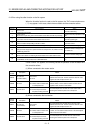
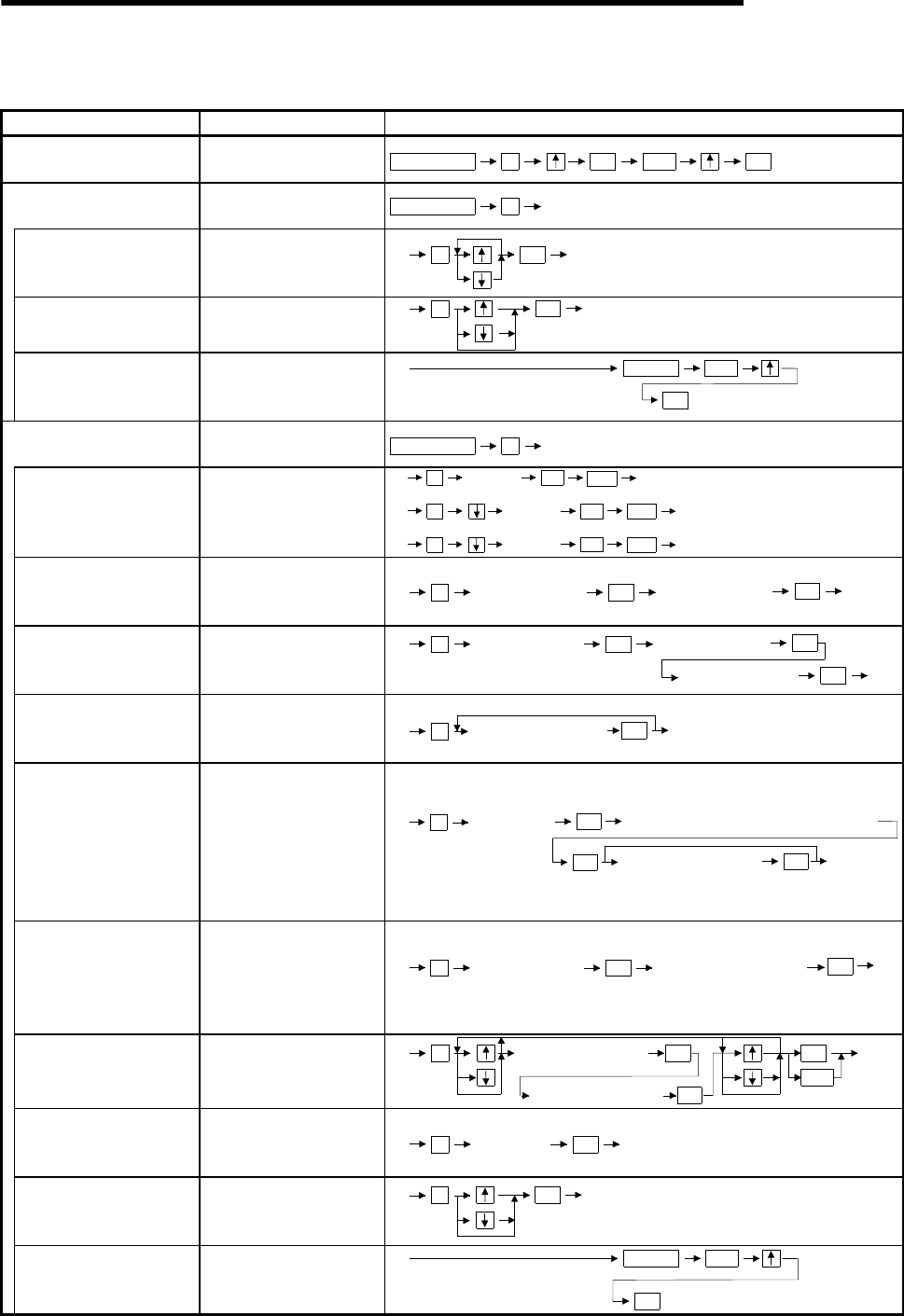
20.3.6 Operation in Parameter mode (P)
Details Purpose Procedures (key input sequence)
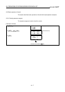
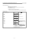
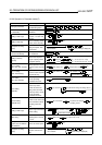
Clearing all parameters
Return the parameters to
the initial setting status.
PARAM
END
GO
GO1
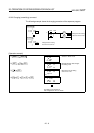
Parameter setting
(for A0J2HCPU)
Set the parameters for the
A0J2HCPU.
PARAM
2
1)
Setting of latch range
Select the latch range from
"No latch", "1/2 latch" and
"All latch".
GO
1
1) 2)
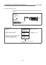
Setting of step relay
Set the availability (S1536
to 2047) of the step relay.
GO
2
1)
2)
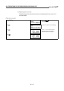
Completion of setting
(write)
When the parameter
setting is complete, write
the PLC CPU.
ENDCLEAR
2)
Setting for multiple items is
also available.
GO
(End of writing is displayed.)
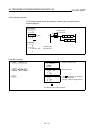
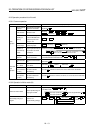
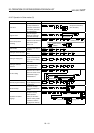
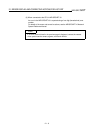
Parameter setting
(other than A0J2HCPU)
Set the parameters other
than A0J2HCPU.
PARAM
2
1)
Setting of memory
capacity
Set the main sequence
program capacity and the
file register capacity.
GO
END
2)1)
1
Capacity
(For main, input unit: 1K step)
Capacity
1)
1
GO
END 2)
(For sub, input unit: 1K step)
points
1)
1
GO
END 2)
(For file register, input unit: 1K point)
M, L, S setting
(other than AnA, AnUCPU)
Set the top device number
used in the latch relay/step
relay.
Top number of L
1)
2
GO
2)
Top number of S
GO
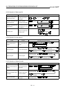
M, L, S setting
(AnA, AnUCPU only)
Set the top device number
used in the latch relay/step
relay/internal relay.
Top number of L
1)
2
GO
Top number of S
GO
2)
To
p
number of M
GO
Timer setting
(other than AnACPU)
Set the top device used in
the low speed/high
speed/retentive timers.
Top number of timer
1)
3
2)
GO
Timer setting
(AnACPU)
Set the number of timers
used, the top device
number that stores the
setting value after T256,
and the top device used in
the low speed/high
speed/retentive timers.
No. of timers
1)
3
GO Top device for storage of setting values
GO
Top number of timer
2)
GO
Counter setting
(AnACPU only)
Set the number of
counters used, and the top
device number that stores
the setting value after
C255.
No. of counters
1)
4
GO Top device for storage
of setting values
GO 2)
Setting of latch range
Set the range of the device
for latch setting.
GO
END
2)
5
1)
Top number of latch
GO
End number of latch
GO
WDT setting
Set the value of the
watchdog timer in the unit
of 10 ms.
GO 2)
1)
6
WDT value
(input unit: 10 ms)
Setting of I/O control
system (only for A3HCPU
and A3MCPU)
Set the I/O control system.
GO
7
1)
2)
Completion of setting
(write)
When parameter setting is
complete, write the PLC
CPU.
END
CLEAR
2)
Setting for multiple items is
also available.
GO
(End of writing is displayed.)