


12. OPERATION OF EACH SPECIAL MODULE MONITOR SCREEN
12 - 70
MELSEC
GOT
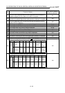
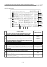
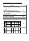
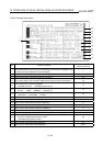
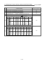
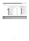
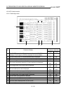
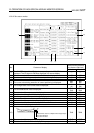
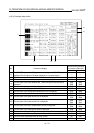
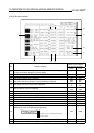
12.21.3 Parameter data monitor
1)
2
)
14
)
15
)
5)
7)
8)
12)
16)
16)
4)
3)
6)
10)
9)
11)
13)
Buffer memory address
to reference (decimal)
No. Contents of display
X axis Y axis
1)
The ON/OFF status of the I/O signal corresponding to the PLC CPU is
displayed.The I/O signal is ON when displayed in a reverse display.
2) The set manual pulser run enabled/disabled status is displayed. 47 347
3) The set value of the travel distance per 1 pulse is displayed. 7873 7893
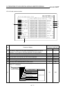
4)
The set value of the travel distance per 1 pulse using the manual pulser is
displayed.
7884
7885
7904
7905
5) The set value of the speed limit is displayed. 7874 7894
6) The set value of the jog speed limit is displayed. 7875 7895
7) The set value of the acceleration/deceleration time is displayed. 7876 7896
8) The set value of the backlash compensation amount is displayed. 7877 7897
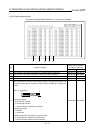
9) The set value of the upper stroke limit is displayed.
7878
7879
7898
7899
10) The set value of the lower stroke limit is displayed.
7880
7881
7900
7901
11) The set value of the error compensation amount is displayed.
7882
7883
7902
7903
12) The set value of the starting bias speed is displayed. 7886 7906
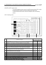
13) The set value of the positioning complete signal output time is displayed. 7887 7907
14) The set value of the M code is displayed. 46 346
15) The error code is displayed when an error occurs. 45 345
16) The set status of the parameter data is displayed. 7872 7892