


12. OPERATION OF EACH SPECIAL MODULE MONITOR SCREEN
12 - 61
MELSEC
GOT
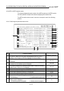
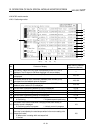
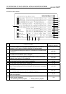
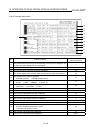
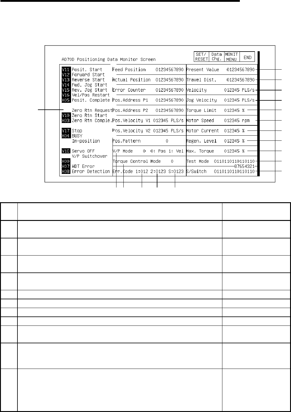
12.20 A70D module monitor
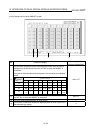
12.20.1 Positioning monitor
2)
1)
13
)
15)
18)
17)
16)
3)
4)
5)
6)
7)
8)
9)
14
)
19)
20)
21)
22)
23)
24)
12
)
10
)
11
)
25)
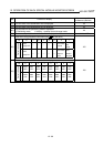
No. Contents of display
Buffer memory address
to reference (decimal)
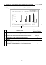
1)
The ON/OFF status of the I/O signal corresponding to the PLC CPU is
displayed. The I/O signal is ON when displayed in a reverse display.
2)
The calculated command pulse number (PLS) based on the command value
is displayed.
100, 101
3)
The actual amount of servo movement (feedback pulse number) (PLS)
calculated from the feedback pulse is displayed.
102, 103
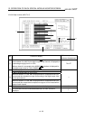
4)
The difference between the command pulse number x CMS/CDV and the
feedback pulse number (PLS) is displayed.
104, 105
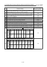
5) The set value of positioning address P1 (PLS) is displayed. 61, 62
6) The set value of positioning address P2 (PLS) is displayed. 65, 66
7) The set value of positioning velocity V1 is displayed. 63, 64
8) The set value of positioning velocity V2 is displayed. 67, 68
9)
The set status of the positioning pattern is displayed.
0: Positioning 1: 2-speed trapezoid positioning
60
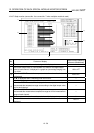
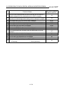
10)
The status of the control mode when changing modes from velocity to
position control is displayed.
0: Positioning control in progress 1: Velocity control in progress
119
11)
This displays whether the torque command (electrical current command) for
the motor is controlled by the rated torque written in the motor catalog x the
"torque limit value".
0: When motor is rotating within set torque limit
1: Limited
120