


1. OVERVIEW
1 - 3
MELSEC
GOT
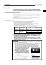
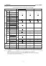
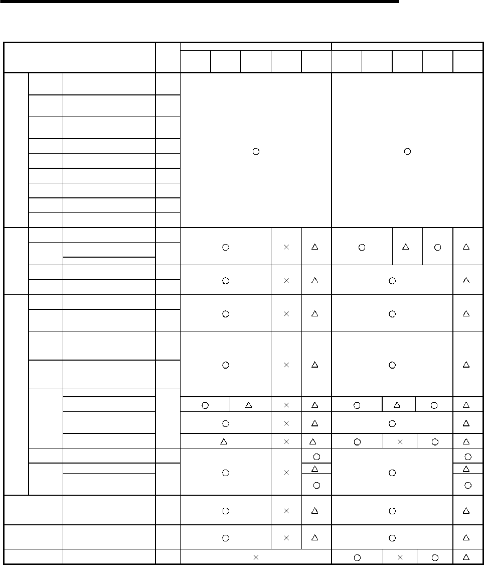
(b) Connection with QnACPU or ACPU
QnACPU ACPU
Functions
Ref.
Section
Bus
connection
CPU direct
connection
Computer
link
connection
MELSEC
NET
connection
CC-Link
connection
Bus
connection
CPU direct
connection
Computer
link
connection
MELSEC
NET
connection
CC-Link
connection
Brightness/
contrast
adjustment
Adjusting the brightness/contrast
of a monitor screen
Section
4.3
Message
display
selection
Selecting a message display.
Section
4.3
Screen &
OS copy
Copying the screen and OS data
between the internal memory and
memory card.
Section
4.4
Setup
Setting a use environment of the
GOT
Section
4.5
Self-test
Running diagnostic checks on
GOT hardware
Section
4.6
Memory
information
Displaying GOT memory
information.
Section
4.7
Clock Setting the clock.
Section
4.8
Screen
cleanup
Displaying the display area
cleanup screen.
Section
4.9
Utility
function
Password
Defining a password for limited
access to the utility menu screen.
Section
4.10
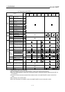
Ladder
monitor
Sequence program monitoring
using ladder signals
Section
6.2.1
Decimal and hexadecimal display
of word device values
Display
switching
Device comment display
Section
6.2.3
∗
2
∗
1
∗
2
Device
changing
Changing of device values
Section
6.2.4
Ladder
monitor
function
Print out Printing of ladder
Section
6.2.5
∗
2
∗
2
Entry
monitor
Monitoring of current values by
pre-registering monitor devices
Section
9.2
Batch
monitor
Monitoring of n points of current
values subsequent to specified
device
Section
9.3
∗
3
∗
3
T/C monitor
Monitoring of m points of current
values, set values, contact points,
and coils subsequent to specified
device
Section
9.4
BM monitor
Monitoring of x points of current
values subsequent to specified
buffer memory of specified special
module
Section
9.5
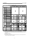
Setting/resetting of bit device
∗
2
∗
2
Changing of current value for
buffer memory of word device
∗
5
∗
2
∗
5
∗
2
Changing of current value for T/C
(can be used while monitoring
T/C)
∗
2
∗
2
Data
editing
using test
operation
Changing of set value for T/C (can
be used while monitoring T/C)
Section
9.6
∗
6
∗
1
∗
6
∗
2
Quick test
Changing of device values using
quick test
Section
9.6.2
Device comment display
∗
2
∗
2
System
monitor
function
Display
switching
Decimal and hexadecimal display
of word device values and buffer
memory values
Section
9.1.2
Special module
monitor function
Monitoring of buffer memory of
special module on special screen
Ch. 11
∗
2
∗
2
Network monitor
function
Monitoring of network status of
MELSECNET/B, (II) or /10
Ch. 15
∗
2
∗
2
List editor function
Sequence program in the ACPU is
list edited.
Ch. 19
∗
2
*1 Subprograms 2 and 3 are not possible.
*2 Can be monitored only when the A8GT-J61BT13 is used (in the intelligent device station).
*3 When the A8GT-J61BT15 is used (in the remote device station), only the link devices assigned to the GOT can
be monitored.
*4 Can't monitor T/C set values.
*5 Can't change V or Z current values.
*6 If you modified the set value for T/C using the ladder monitor test function, you need to repeat the PC readout
procedure to enable the display of the modification.