


12. OPERATION OF EACH SPECIAL MODULE MONITOR SCREEN
12 - 114
MELSEC
GOT
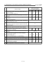
Buffer memory address
to reference (hexadecimal)
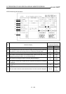
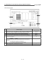
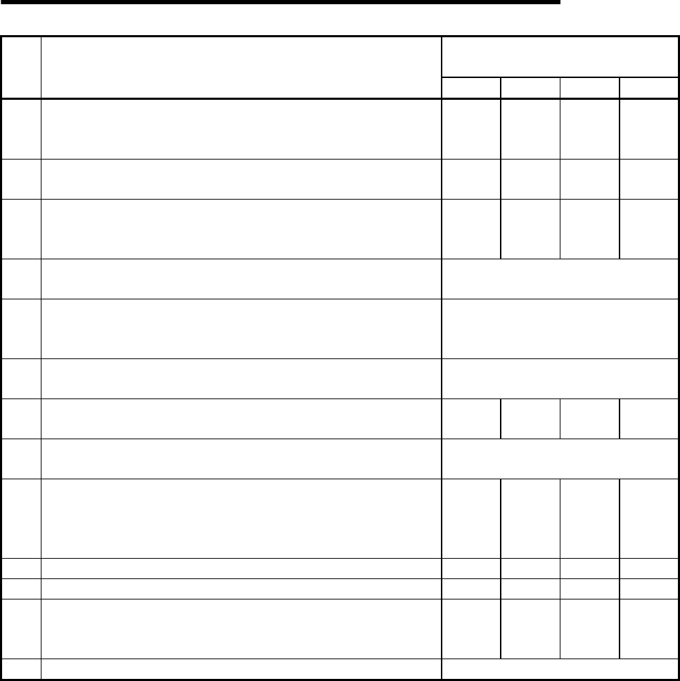
No. Contents of display
CH1 CH2 CH3 CH4
7)
The ratio range (P) which is set in the PID constant setting of each
channel is displayed.
When 0, the 2-position control is set.
23 43 63 83
8)
The integral time (I), set in the PID constant setting of each channel is
displayed.
24 44 64 84
9)
The derivative time (D), set in the PID constant setting of each channel
is displayed.
When 0, the PI control is set.
25 45 65 85
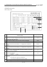
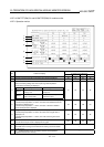
10)
A "
!
" is displayed when out-of-range data is stored in the temperature
adjustment module buffer memory.
11)
The buffer memory address for which an error was detected during the
performance of a write to the temperature adjustment module buffer
memory is displayed.
0
12)
The details of the error detected during the performance of a write to
the temperature adjustment module buffer memory is displayed.
0
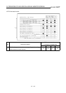
13)
The temperatures for which the warning alarms 1 to 4 set for each
channel turns on are displayed.
26 to 29 46 to 49 66 to 69 86 to 89
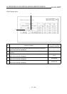
14)
The warning mode of warning alarm 1 to 4 set for each channel are
displayed.
A0 to A3
15)
The current sensors connected to each channel are displayed.
0: When using CTL-12-S36-8
1: When using CTL-6-P
(When using A1S64TCRTBW-S1 or A1S64TCTTBW-S1)
39 59 79 99
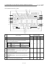
16) The heater currents detected for each channel are displayed. 19 1A 1B 1C
17) The standard heater current values set for each channel are displayed. AB AC AD AE
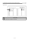
18)
The upper/lower limits for when the movement value (MV) which are
calculated with the PID calculation set for each channel is outputted to
the external device are displayed.
2A
2B
4A
4B
6A
6B
8A
8B
19) A "
!
" is displayed when a warning occurs for each channel.