12. OPERATION OF EACH SPECIAL MODULE MONITOR SCREEN
12 - 100
MELSEC
GOT
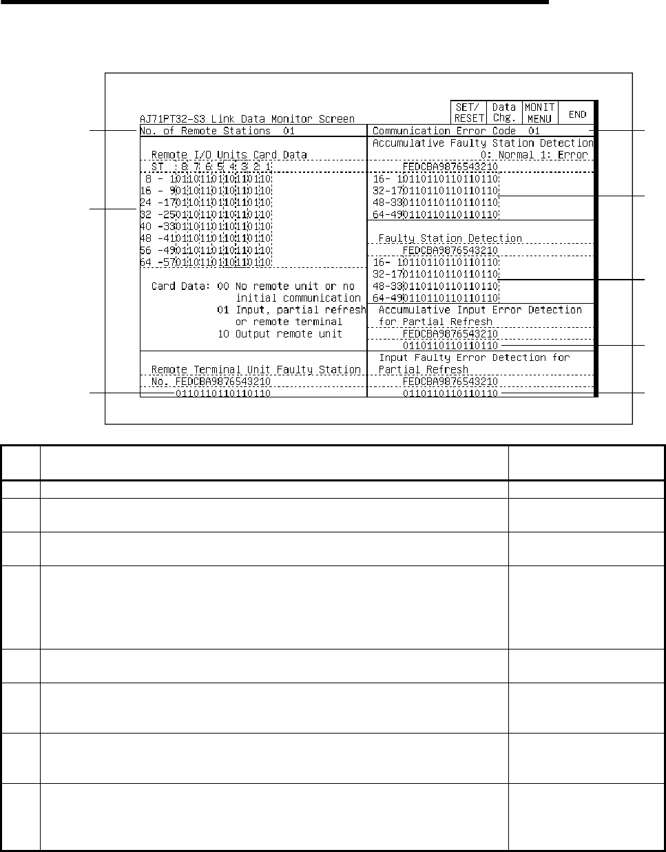
12.24.2 Monitoring the link status
1)
2
)
3)
4)
5)
6)
7)
8)
No. Contents of display
Buffer memory address
to reference (decimal)
1) The total number of remote stations connected is displayed. 0
2)
This shows whether the station number of the connected remote module is for input or
output.
70 to 77
3)
A "1" is displayed for the remote terminal module number where the error has
occurred.
195
4)
When an error occurs in link communications, the communications error code is
displayed.
0: No error 1: Initial data error
2: Ladder error 3: Erroneous station issued
4: Separate refresh type remote I/O module error
107
5)
A communications error has occurred, and a "1" is displayed for the station number of
the remote module. The detection status is maintained until the error is reset.
90 to 93
6)
A communications error has occurred, and a "1" is displayed for the station number of
the remote module. If the automatic recovery function is on, a "0" is displayed when
normal communications have been resumed.
100 to 103
7)
A "1" is displayed for the station number of a separate refresh type remote I/O module
where the input information could not be read out within a given time period. The
detection status is maintained until the error is reset.
598
8)
A "1" is displayed for the station number of a separate refresh type remote I/O module
where the input information could not be read out within a given time period. If the
automatic recovery function is on, a "0" is displayed when the station is able to read
the input normally.
599


