


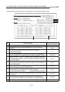
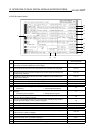
12. OPERATION OF EACH SPECIAL MODULE MONITOR SCREEN
12 - 59
MELSEC
GOT
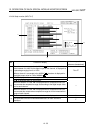
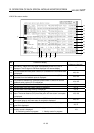
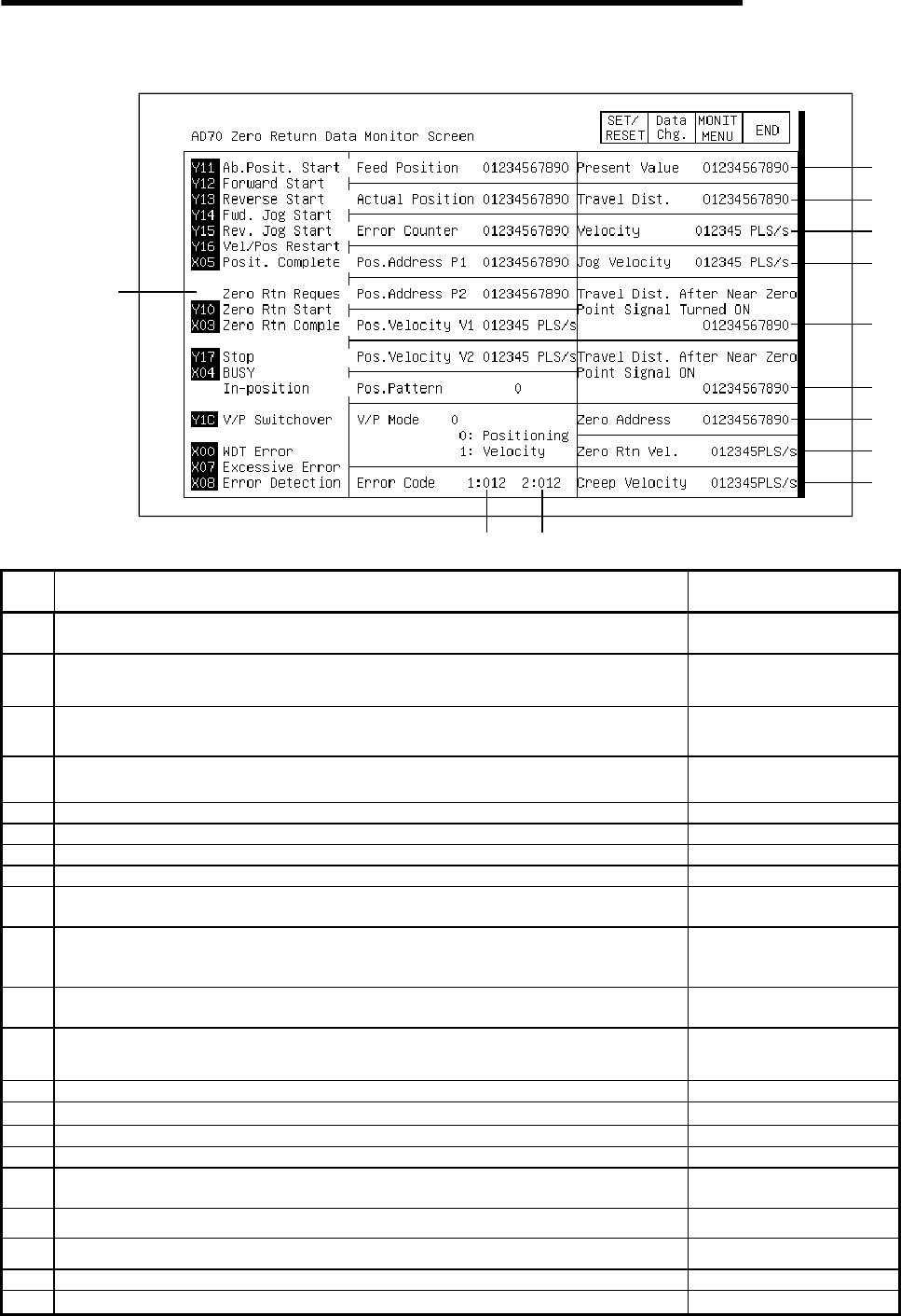
12.19.2 Zero return monitor
1)
11)
13)
16)
15)
14)
2)
3)
4)
5)
6)
7)
8)
9)
12)
10)
17)
18)
19)
20)
21)
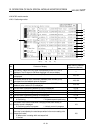
No. Contents of display
Buffer memory address to
reference (decimal)
1)
The ON/OFF status of the I/O signal corresponding to the PLC CPU is displayed.
The I/O signal is ON when displayed in a reverse display.
2) The calculated command pulse number (PLS) based on the command value is displayed. 100, 101
3)
The actual amount of servo movement (feedback pulse number) (PLS) calculated from the
feedback pulse is displayed.
102, 103
4)
The difference between the command pulse number x CMS/CDV and the feedback pulse
number (PLS) is displayed.
106, 107
5) The set value of positioning address P1 (PLS) is displayed. 61, 62
6) The set value of positioning address P2 (PLS) is displayed. 65, 66
7) The set value of positioning velocity V1 is displayed. 63, 64
8) The set value of positioning velocity V2 is displayed. 67, 68
9)
The set status of the positioning pattern is displayed.
0: Positioning 1: 2-speed trapezoid positioning
60
10)
The status of the control mode when changing modes from velocity to position control is
displayed.
0: Positioning control in progress 1: Velocity control in progress
111
11)
The error code is displayed when an error occurs that can be handled by a sequence program
such as a data error or BUSY in progress.
104
12)
The error code is displayed when an error occurs that causes monitoring to stop due to an
external signal when starting or when a startup is in progress.
105
13) The change value (PLS) of the current value is displayed. 80, 81
14) The change value (PLS) of the speed/position/travel distance is displayed. 88, 89
15) The change value of the speed change is displayed. 82, 83
16) The set value of JOG speed is displayed. 84, 85
17)
After zero return starts, the travel distance (PLS) from when the near zero point signal goes on
until zero return is complete is displayed.
108, 109
18) The set value (PLS) of the travel distance after the near zero point signal goes on is displayed. 46, 47
19) The set value (PLS) of the zero address is displayed. 40, 41
20) The set value of the zero return velocity is displayed. 42, 43
21) The set value of the creep velocity is displayed. 44, 45