12. OPERATION OF EACH SPECIAL MODULE MONITOR SCREEN
12 - 38
MELSEC
GOT
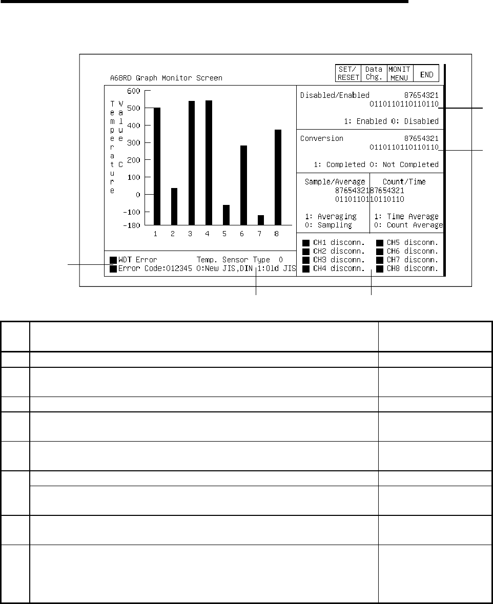
12.14.3 Graph monitor
6)
7
)
2)
3)
8
)
1)
4) 5)
No. Contents of display
Buffer memory address
to reference (decimal)
1) The temperature detection value of each channel is displayed in a graph. 10 to 17
2)
The specified conversion enabled/disabled status of each channel is
displayed.
0
3) The conversion complete flag status for each channel is displayed.. 35
4)
The specified status for the averaging processing/sampling processing of
each channel is displayed.
1
5)
The specified status for the averaging processing of each channel is
displayed.
1
A "
!
" is displayed when a watchdog timer error occurs.
6)
A "
!
" is displayed when a writing data error occurs; the channel where it
occurred and the error code are displayed.
34
7)
The specified status of the platinum temperature sensor that is used is
displayed.
36
8)
For A68RD3
A "
!
" is displayed in a channel where a broken wire was detected.
For A68RD4
A "
!
" is displayed in CH1 when a broken wire is detected in any channel.


