


12. OPERATION OF EACH SPECIAL MODULE MONITOR SCREEN
12 - 113
MELSEC
GOT
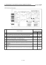
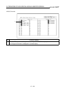
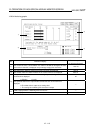
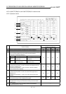
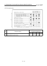
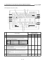
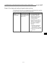
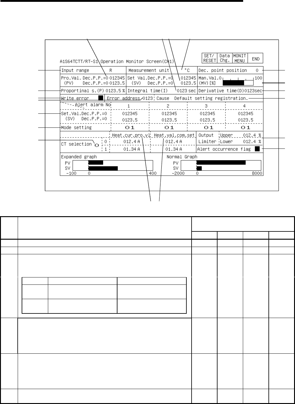
12.27.3 Operation monitor (CH1 to CH4)
1)
16
)
4)
7)
10)
11)
13)
14)
15)
17
)
8) 5) 2)
19)
18)
12)
9)
6)
3)
Buffer memory address
to reference (hexadecimal)
No. Contents of display
CH1 CH2 CH3 CH4
1) The type of the thermocouple connected to each channel is displayed. 20 40 60 80
2) The temperature measurement unit set for each channel is displayed. 20 40 60 80
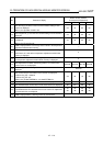
The decimal position information of the temperature measurement value, goal
value, and warning setting value for the input range and temperature
measurement unit setting are displayed.
Display When reading from PLC CPU When writing from PLC CPU
When 0
Use the data from buffer
memory as is.
Write the value to be specified
directly as is.
When 1
Use the 1/10th of the data read
as actual value.
Write the value to be specified
as 10 times the value.
3) 01 02 03 04
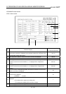
4)
The measured temperature (PV value) detected for each channel is displayed.
In the decimal point position = 0 column, the value of the detected measured
temperature is displayed as is.
In the decimal point position = 1 column, the value 1/10th of the detected
measured temperature is displayed.
09 0A 0B 0C
5)
The goal value (SV value) set for each channel is displayed.
In the decimal point position = 0 column, the value of the set goal value is
displayed as is.
In the decimal point position = 1 column, the 1/10th of the set goal value is
displayed.
22 42 62 82
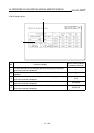
6)
The PID-calculated values (-5.0% to 105.0%) of the temperature values read
from the thermocouple of each is displayed in the graph.
0D 0E 0F 10