


9. OPERATION OF THE VARIOUS SYSTEM MONITOR SCREENS
9 - 5
MELSEC
GOT
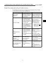
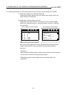
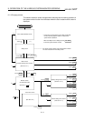
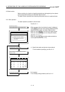
NETWK No.[ 0] STATION[FF]
DEVICE[
D] [ ] 16b:0 32b:1 [0]
XYML
AC
B
G
F
Z
D
V
W
TCA
E
DEL
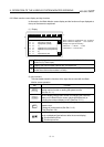
1)
Arrow: Select input area.
( : Left / right)
Character: Input network no., station, device name,
device no.
0 1 : Enter monitor module.
(*2)(*3)
(Touch: input confirmation)
Entry monitor for specified device
R
S
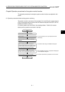
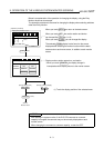
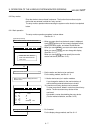
1) Specify network No. and station No. of object PLC CPU.
(*1)
(For data link system)
NET WK No.: 0
STATION : FF (Host station)
0 (Master station)
1 to 64 (Local station)
(For network system)
NET WK No.: 0 (Host loop)
1 to 255 (Specified loop)
STATION : FF (Host station)
0 (Control station)
1 to 64 (Normal station)
(2) Specify the device to be monitored.
(3) When specifying the word device or buffer memory as
a monitor device, specify the monitor module.
0: 16-bit (1-word) module
1: 32-bit (2-word) module
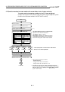
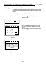
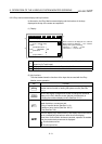
* Match the data to be entered; the touch key display at the
bottom of the screen will change.
(EX.)
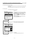
NETWK No.[ ] STATION[FF]
DEVICE[ ] [ ] 16b:0 32b:1 [0]
7
4
1
0
8
5
2
−
9
6
3
#
A
C
E
AC
B
D
F
DEL
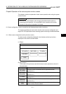
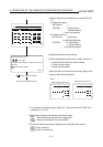
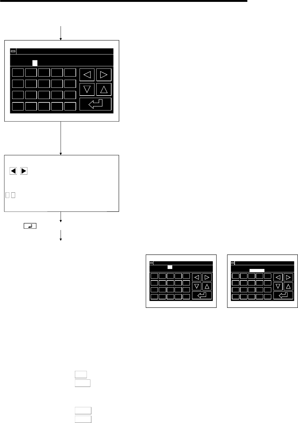
NETWK No.[ 0] STATION[FF]
DEVICE[ D] [ 50 ] 16b:0 32b:1 [0]
7
4
1
0
8
5
2
−
9
6
3
#
A
C
E
AC
B
D
F
DEL
(When entering network no.)
(When entering device no.)
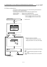
*1 For the station, with either system, specify "FF", which shows the PLC CPU to be
accessed, or "0" to "64".
*2 Data being entered can be cleared by the following keys.
AC
: Clears all data being entered to the target area.
DEL
: Clears one character at the cursor position.
*3 The form of data to be entered is displayed at the right side of the screen.
DEC
: Enter in decimal
HEX
: Enter in hexadecimal