


12. OPERATION OF EACH SPECIAL MODULE MONITOR SCREEN
12 - 51
MELSEC
GOT
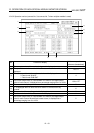
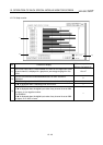
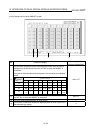
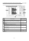
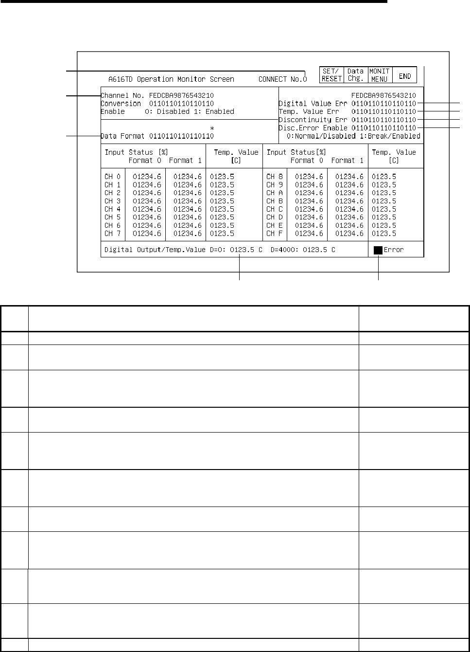
12.18.2 Operation monitor (connect No. 0 to connect No. 7 when multiplex module is used)
3)
10
)
5)
8)
11
)
9)
7)
6)
4)
2)
1)
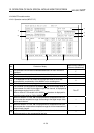
No. Contents of display
Buffer memory address to
reference (hexadecimal)
1) The connect number of the monitor being used is displayed.
2)
The specified conversion enabled/disabled status for each channel is
displayed.
10 to 17
3)
The set status of the data format for each channel is displayed.
0: Data format 48-4047
1: Data format 2048-4047
0
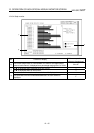
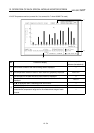
4)
The current output value, a value between 0 to 4000 for the digital output
value of each channel, is displayed as a percentage ranging from 0 to 100%.
180 to 1FF
5)
When the A60MXT is used, "1" is displayed when a temperature was input
that exceeds the temperature range set according to the digital output value
set for each channel.
50 to 57
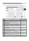
6)
When the A60MXT is used, "1" is displayed when a temperature was input
that exceeds the measurement temperature range set for the measurement
range of each channel.
60 to 67
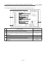
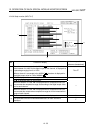
7)
When the A60MXT is used, "1" is displayed when broken wire is detected in
the thermocouple or the compensating lead wire.
40 to 47
8)
When the A60MXT is used, the set status of the broken wire detection for the
thermocouple that is connected to each channel is displayed.
0: Broken wire detection disabled 1: Broken wire detection enabled
20 to 27
9)
When the A60MXT is used, the temperature detection value of each channel
is displayed.
200 to 27F
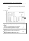
10)
The set temperature value (when the digital value is 0 or 4000) of the
channel to which the A60MXT being monitored is connected is displayed.
30 to 3F
11) A "
!
" is displayed when an error occurs.