


12. OPERATION OF EACH SPECIAL MODULE MONITOR SCREEN
12 - 107
MELSEC
GOT
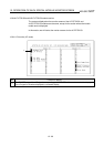
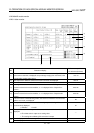
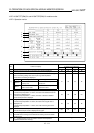
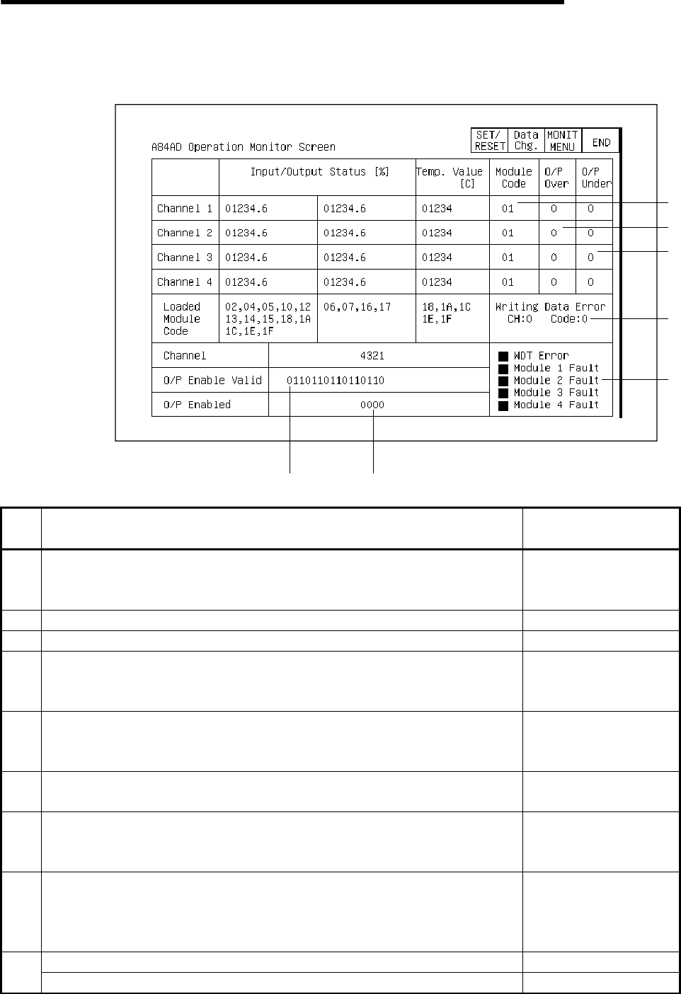
12.26 A84AD module monitor
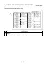
12.26.1 Action monitor
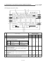
1)
7
)
8
)
3)
4)
5)
6)
9)
2)
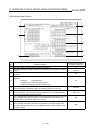
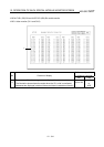
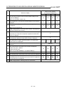
No. Contents of display
Buffer memory address
to reference (decimal)
1)
The current I/O data, a value between 0 to 1000 or 0 to 2000 for the digital I/O value
of the various channels, is displayed as a percentage ranging from 0 to 100%, in the
corresponding module code column.
10 to 13
2) The temperature detection values for the various channels are displayed. 18 to 21
3) The codes for installed modules for the various channels are displayed. 28 to 31
4)
If the digital values for the various channels have been set to values larger than the
maximum value for the various modules, a "1" is displayed in the "Output Over"
column.
22 to 25
5)
If the digital values for the various channels have been set to values smaller than the
maximum value for the various modules, a "1" is displayed in the "Output Under"
column.
22 to 25
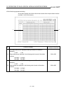
6)
If an error occurs in the data being written, the channel on which the error occurred,
and the error code, are displayed.
26
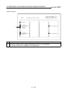
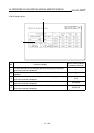
7)
The specified effective/invalid status for the analog output enable signal for each of
the channels is displayed.
0: Effective 1: Invalid
27
8)
The specified status for the output enable command of each of the channels is
displayed.
0: The offset value is output as an analog value.
1: The analog value following D/A conversion is output.
A "
!
" is displayed when a watchdog timer error occurs.
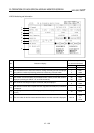
9)
A "
!
" is displayed when an error occurs in a module on the various channels.