10. COMMUNICATION INTERFACE SETTING (COMMUNICATION SETTING)
10.1 Communication setting
10 - 3
9
UTILITY FUNCTION
10
COMMUNICATION
INTERFACE SETTING
(COMMUNICATION SETTING)
11
DISPLAY AND
OPERATION SETTINGS
(GOT SET UP)
12
CLOCK SETTINGS AND
BATTERY STATUS DISPLAY
(TIME SETTING AND DISPLAY)
13
FILE DISPLAY AND
COPY (PROGRAM/DATA
CONTROL)
14
GOT SELF CHECK
(DEBUG AND SELF
CHECK)
15
CLEANING DISPLAY
SECTION (CLEAN)
16
INSTALLATION OF
COREOS, BOOTOS
AND STANDARD
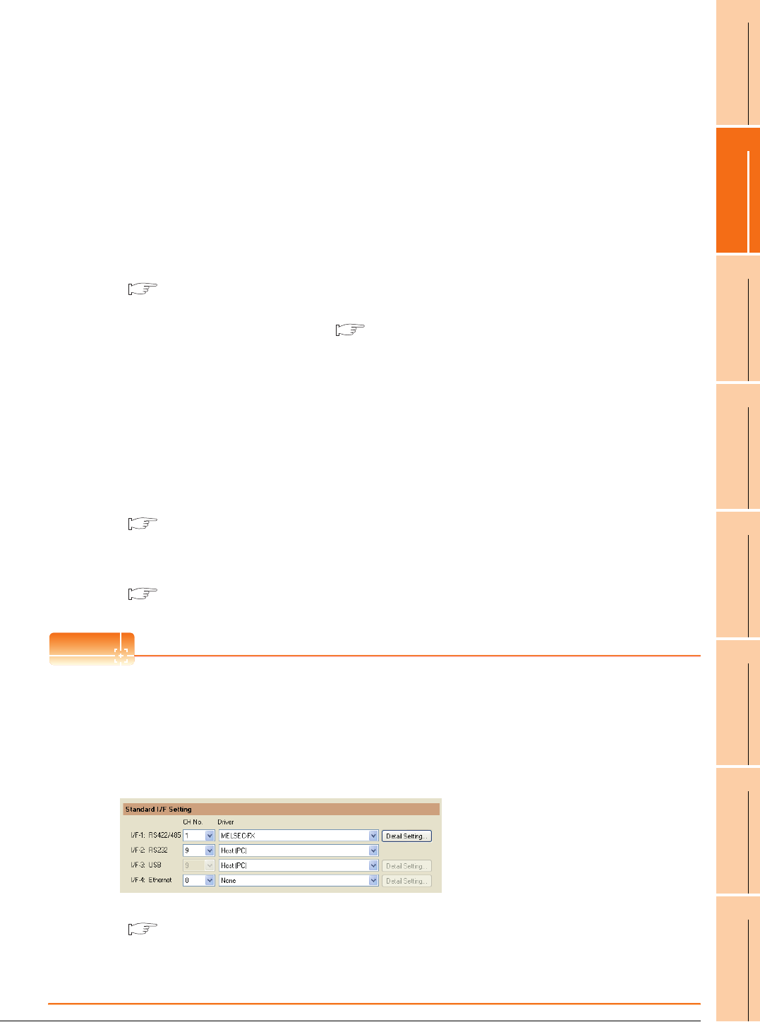
(3) Channel number specification menu BOX
Set channel No. to use with standard interface.
Refer to this section (4) for driver that can be assigned to each channel.
• Fixed to 9 for the USB interface.
*1 Cannot be assigned with Ethernet I/F Assignment.
(4) Driver display BOX
The name of communication driver assigned to the channels or the driver set with the Communication Setting of
drawing software is displayed.
For details of drivers to be displayed, refer to the following manual.
GT Designer3 Version1 Screen Design Manual (Fundamentals)
Displays [None] in the driver display BOX in case of the following.
• The communication driver is not installed. (
13.2.1 OS information)
• In channel number specification menu BOX, [0] is set.
When the channel number is set to [9] to RS-232 interface, the communication driver [Host (PC)] or [Host
(model)] can be selected.
When the channel number is set to [9] to USB interface, the communication driver [Host (PC)] is automatically
assigned.
(5) Assign Ethernet I/F
The communication settings for the Ethernet connection can be made.
Only Ethernet interface built-in model can display this button.
Ethernet I/F Assignment can assign up to two channels per interface.
10.1.4
■ Assign Ethernet I/F operation
(6) 5V power supply
Set the 5V power supply when using the RS-232/485 signal conversion adaptor.
10.1.4
■ 5V power supply operation
POINT
POINT
POINT
Precautions for communications between GOT and controller
(1) Installing communication driver and downloading Communication Setting
The following below is required for the communication interface to communicate with the controller.
1) Installing communication drivers (Up to 4 communication drivers)
2) Assigning the channel number and communication driver for the communication interface
3) Downloading the contents (project data) assigned in 2).
Perform1), 2), 3) by drawing software.
For details, refer to the following.
GT Designer3 Version1 Screen Design Manual (Fundamentals)
(2) When Communication Setting has not been downloaded.
When [Communication Setting] has not been downloaded using drawing software, make the communication
settings in the drawing software or on the utility screen of the GOT.
0: Set when the communication interface is not used.
1, 2: Set when connecting to a controller.
8: Set when connecting with a bar code reader or RFID.
9
*1
:
Set when connecting with PC (drawing software).
*:
Set when using the function that uses the gateway function (when connection types except the
Ethernet connection is used for connecting to controllers), Ethernet download function.


