


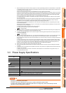

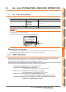

5. UL, cUL STANDARDS AND EMC DIRECTIVE
5.2 EMC Directive
5 - 3
1
OVERVIEW
2
SYSTEM
CONFIGURATION
3
SPECIFICATIONS
4
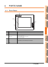
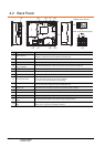
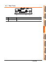
PARTS NAME
5
UL, cUL
STANDARDS AND
EMC DIRECTIVE
6
INSTALLATION
7
WIRING
8
OPTION
Control panel
GOT
is an open type device (device installed to another device) and must be installed in a conductive control panel.
It not only assure the safety but also has a large effect to shut down the noise generated from GOT, on the control
panel.
(1) Control panel
(a) The control panel must be conductive.
(b) When fixing a top or bottom plate of the control panel with bolts, do not coat the plate and bolt surfaces so
that they will come into contact.
And connect the door and box using a thick grounding cable in order to ensure the low impedance under
high frequency.
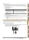
(c) When using an inner plate to ensure electric conductivity with the control panel, do not coat the fixing bolt
area of the inner plate and control panel to ensure conductivity in the largest area as possible.
(d) Ground the control panel using a thick grounding cable in order to ensure the low impedance under high
frequency.
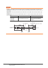
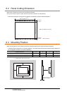
(e) Holes made in the control cabinet must be 10 cm (3.94inch) diameter or less. If the holes are 10cm
(3.94inch) or larger, radio frequency noise may be emitted.
In addition, because radio waves leak through a clearance between the control panel door and the main
unit, reduce the clearance as much as practicable.
The leakage of radio waves can be suppressed by the direct application of an EMI gasket on the paint
surface.
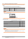
(2) Connection of power and ground wires
Ground and power supply wires for the GOT must be connected as described below.
Provide a grounding point near the GOT. Short-circuit the FG terminals of the GOT (FG: frame ground) and
ground them with the thickest and shortest wire possible (The wire length must be 30cm (11.81in.) or shorter.)
The FG terminals function is to pass the noise generated in the PC system to the ground, so an impedance that
is as low as possible must be ensured. As the wires are used to relieve the noise, the wire itself carries a large
noise content and thus short wiring means that the wire is prevented from acting as an antenna.
Note) A long conductor will become a more efficient antenna at high frequency.
(3) Shock protection
In order to prevent those who are unfamiliar with power facility, e.g., an operator, from getting a shock, make
sure to take the following measures on the control panel.
(a) Store the GOT within the control panel locked, and allow only those who are familiar with power facility to
unlock the panel.
(b) Build the structure in order that the power supply will be shut off when the control panel is opened.
(4) Dustproof and waterproof features
The control panel also provides protection from dust, water and other substances. Insufficient ingression
protection may lower the insulation withstand voltage, resulting in insulation destruction. The insulation in the
GOT is designed to cope with the pollution level 2, so use in an environment with pollustion level 2 or better.
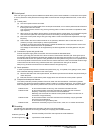
Grounding
The following are applicable ground terminals. Use them in the grounded state.
Be sure to ground the GOT for ensuring the safety and complying with the EMC Directive.
Pollution level1 : An environment where the air is dry and conductive dust does not exist.
Pollution level2 : An environment where conductive dust does not usually exist, but occasional
temporary conductivity occurs due to the accumulated dust.
Generally, this is the level for inside the control panel equivalent a control room or
on the floor of a typical factory.
Pollution level3 : An environment where conductive dust exits and conductivity may be generated
due to the accumulated dust.
An environment for a typical factory floor.
Pollution level4 : Continuous conductivity may occur due to rain, snow, etc. An outdoor environment.
Protective grounding :
Ensures the safety of the GOT and improves the noise resistance.
Functional grounding :
Improves the noise resistance.