


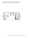
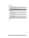

Agilent 35670A Rear Panel
1-The GPIB connector links the Agilent 35670A to other GPIB devices. GPIB parameters are set in the [
Local/GPIB
] and
[
Plot/Print
] menus.
2-The SERIAL PORT and the PARALLEL PORT link the analyzer to plotters and printers. These parameters are set in the
[
Plot/Print
] menu.
3-The SOURCE connector outputs the analyzer’s source signal. An LED on the front panel indicates if the source is on or off. The
source parameters are set in the [
Source
] menu.
The standard Agilent 35670A (2-channel) also has a source connector on the front panel.
4-The EXT TRIG connector links the analyzer to an external trigger signal. The external trigger parameters are set in the [
Trigger
]
menu.
5-The TACH connector links the analyzer to a tachometer. The tachometer parameters are set in the [
Input
] menu.
6-The KEYBOARD connector attaches an optional keyboard to the analyzer.
7-The DC POWER connector accepts DC power levels from 12 - 28 Vdc (nominal).
8-The AC POWER connector accept a wide range of ac voltage levels.
9-The POWER SELECT switch determines whether the analyzer is powered via the AC POWER connector or the DC POWER
connector.
10-The EXT MONITOR port links the analyzer to multi-sync monitors.