


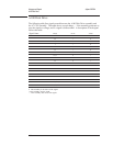
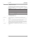

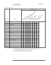
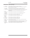

Power-on Test Messages
The ‘’Power-on Test Messages’’ table provides additional information for interpreting
the power-on test LEDs. Using the ‘’Binary to Hexadecimal’’ table, translate the
power-on test LEDs to their equivalent hexadecimal code (see ‘’To troubleshoot
power-up failures’’ on page 4-15 for details on decoding the power-on test LEDs to
their binary code). The ‘’Power-on Test Messages’’ table describes the power-on
subtests in the order they are run. The table also shows the relationship between a
failing power-on subtest and the assemblies or sub-blocks.
False error codes can be caused by shorts on the buses, reset line, or interrupt line. If
an error code is caused by the last bus connected, it is probably the source of the
failure.
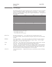
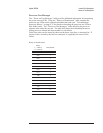
Binary to Hexadecimal
Binary
1 = LED on
0 = LED off
Hexadecimal
0000 0
0001 1
0010 2
0011 3
0100 4
0101 5
0110 6
0111 7
1000 8
1001 9
1010 A
1011 B
1100 C
1101 D
1110 E
1111 F
Agilent 35670A Internal Test Descriptions
Power-on Test Description
10-3