


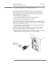
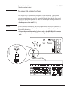
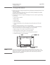

To connect the analyzer to a serial device
The Serial Port is a 9-pin, EIA-574 port that is only available using option 1C2,
Instrument Basic. The total allowable transmission path length is 50 feet.
•
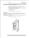
Connect the analyzer’s rear panel SERIAL PORT to a serial device using a 9-pin
female to 25-pin RS-232-C cable.
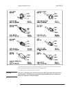
Part Number Cable Description
HP 24542G 9-pin female to 25-pin male RS-232
HP 24542H 9-pin female to 25-pin female RS-232
For additional information, see chapter 9 in the Agilent 35670A Service Guide.
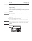
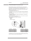
To connect the analyzer to a parallel device
The Parallel Port is a 25-pin, Centronics port. The Parallel Port can interface with
PCL printers or HP-GL plotters.
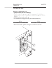
• Connect the analyzer’s rear panel PARALLEL PORT connector to a plotter or printer
using a Centronics interface cable.
Part Number Cable Description
HP 92284A 25-pin male to 36-pin male 2-meter Centronics
HP C2912B 25-pin male to 36-pin male 3-meter Centronics
For additional information, see chapter 9 in the Agilent 35670A Service Guide.
Agilent 35670A Preparing the Analyzer for Use
To connect the analyzer to a serial device
2-11