


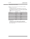

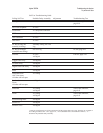

Step 3. Determine the probable faulty assembly and next test by comparing the
analyzer’s symptoms to the following table.
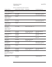
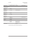
Failure Probable Faulty Assembly Next Test
Disk drive A100 Disk Drive
Flexible disk
Disk drive cable
A7 CPU
Disk drive, page 4-57
GPIB A10 Rear Panel †
Serial port A10 Rear Panel †
Parallel A10 Rear Panel †
External trigger A10 Rear Panel
A5 Analog
Trigger failures, page 4-62
Tachometer A10 Rear Panel
A6 Digital
Tachometer, page 4-24
Source A5 Analog
A6 Digital
Source and calibrator, page 4-45
Autorange
Overrange
A1/A2 Input
A5 Analog
Auto-range, page 4-59
External keyboard A10 F200 fuse
External Keyboard
A10 Rear Panel
DIN connector, page 4-61
External monitor A7 CPU
Microphone power
Microphone adapter
A77 Microphone
A5 Analog
Microphone power, page 4-69
Performance test Performance test, page 4-42
Intermittent failure Intermittent, page 4-40
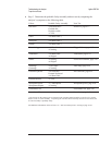
† The circuits for the output ports are located on the A10 Rear Panel assembly except for a few output
buffers on the A7 CPU assembly. If replacing the A10 Rear Panel assembly does not fix the failure, the
A7 CPU assembly is probably faulty.
For additional information on the self tests, see ‘’Self-Test Descriptions’’ starting on page 10-10.
Troubleshooting the Analyzer Agilent 35670A
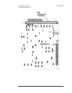
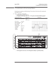
To perform self tests
4-36