


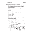
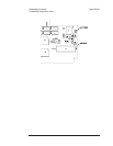


To troubleshoot microphone power and adapter failures
Use this test to isolate Microphone failures to the A5 Analog assembly or option UK4,
Microphone Adapter and Power Supply.
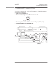
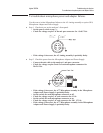
Step 1. Check mic pwr on the analyzer’s front panel.
•
Set the power switch to on ( l ).
•
Check the voltage on pin 2 of the mic pwr connector for +8 ±0.5 Vdc.
•
If the voltage is incorrect, the A5 Analog assembly is probably faulty.
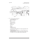
Step 2. Check the power from the Microphone Adapter and Power Supply.
•
Connect the mic cable to the analyzer’s mic pwr connector.
•
Check the voltage on pins 5 and 6 of each microphone connector for
28±2.8 Vdc.
•
If the voltage is incorrect, the A77 Microphone assemby in the Microphone
Adapter and Power Supply is probably faulty.
•
Set the switch for each microphone connector to off.
•
Check the voltage on pin 3 of each connector for 0 Vdc.
•
Set the switch for each microphone connector to on.
•
Check the voltage on pin 3 of each connector for 200 15 Vdc.
•
If the voltage is incorrect, the A77 Microphone assembly in the Microphone
Adapter and Power Supply is probably faulty.
Agilent 35670A Troubleshooting the Analyzer
To troubleshoot microphone power and adapter failures
4-69