


A10 Rear Panel
This section describes the signals at the A10 Rear Panel assembly’s interface
connectors and input connectors. The signals are described in the following order:
GPIB
Serial Port
Parallel Port
DIN Keyboard
Source Output
Tachometer Input
External Trigger Input
GPIB
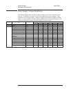
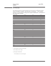
The following table lists signals at the GPIB connector (A10 J102). A general
description of each signal follows the table. For a detailed description of how the
analyzer interprets the GPIB lines, see the Agilent 35670A GPIB Command Reference.
Signal Name
Pin
ATN
11
DAVn
6
DIO1
1
DIO2
2
DIO3
3
DIO4
4
DIO5
13
DIO6
14
DIO7
15
DIO8
16
EOIn
5
IFCn
9
NDACn
8
NRFDn
7
RENn
17
SRQn
10
Shield
12
GND
18–24
ATN Attention — This line is controlled by the controller in charge. When this line is low,
the DIO lines contain interface commands. When this line is high, the DIO lines contain data.
DAVn Data Valid — This line goes low when valid data is on the bus and NRFDn is high. This line is
controlled by the GPIB controller.
Voltages and Signals Agilent 35670A
A10 Rear Panel
9-14