


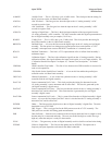

EXTRGIN External Trigger In — This is a buffered version of the A10 Rear Panel assembly’s external
trigger input.
FA1 — FA5 Fast Bus Address Lines — These lines are a buffered form of the A7 CPU assembly’s
microprocessor address bus. The CPU assembly uses these lines to address different circuits on
the A6 Digital assembly.
FAN+ Fan Voltage — This voltage can vary from approximately +12 V to 0 V. This variable voltage
turns the fan on and off and controls the speed of the A90 Fan assembly.
FANFUL Fan Full — A high on this line causes FAN+ to go to its positive limit. When FAN+ is at its
positive limit, the A90 Fan assembly is on and turning at its highest speed.
FANOFF Fan Off — A high on this line causes FAN+ go to its negative limit. When FAN+ is at its
negative limit, the A90 Fan assembly is off.
FANTRIP Fan Trip — A high on this line causes FANOFF to go low which allows the fan to turn on and
cool the analyzer. This line goes high when the fan is turned off and the internal temperature
exceeds a set point.
FD0 — FD15 Fast Bus Data Lines — These bidirectional data lines are a buffered version of the A7 CPU
assembly’s buffered microprocessor data bus. These lines allow communication between the
CPU assembly and A6 Digital assembly.
FDTACKn Fast Bus Data Transfer Acknowledge — A low on this line terminates asynchronous bus
cycles.
FIFOBAVn First In First Out Block Available — This line goes low after the FIFO gate array on the
A6 Digital assembly collects a complete block of data.
FIFOENn First In First Out Enable — This line pulses low in response to a low on FIFOBAVn. This line
enables the transfer of one data word from the A6 Digital assembly’s FIFO gate array to the
A7 CPU assembly over the fast bus.
FIFORDYn First In First Out Ready — This line goes low when a data word is ready to be transferred from
the A6 Digital assembly over the fast bus.
FIRQn Fast Bus Interrupt Request — A low on this line interrupts the A7 CPU assembly.
FRW Fast Bus Read/Write — This line is high during a read cycle and low during a write cycle.
This line is a buffered version of the read/write line (PRW).
FSDIV2 Sample Clock Divided By 2 — This is a 50% duty cycle, 131.072 kHz clock generated by the
A6 Digital assembly to synchronize the A98 Power Supply assembly. The Power Supply
assembly phase locks its switching frequency to this clock.
Voltages and Signals Agilent 35670A
A99 Motherboard
9-30