


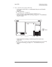

Step 7. Check signals required for power up.
•
Using a logic probe, check the following signals.
Signal Name Test Location TTL State Probable Faulty Assembly
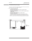
PVALID A7 P8 pin 3 High A98 Power Supply
RSTn A7 P8 pin 5 High A7 CPU
CASn A7 P7 pin 3 Toggling A7 CPU
RASn A7 P7 pin 4 Toggling A7 CPU
VDATA A7 P7 pin 7 Toggling A7 CPU
ASn A7 P6 pin 10 Toggling A7 CPU
•
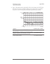
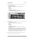
Using a logic probe, check that the following TTL signals are toggling just
after power up.
The signals may stop toggling when the CPU assembly finishes the bootrom self
tests.
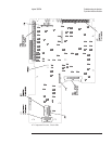
Signal Name Test Location
PASn A7 P8 pin 7
PDSACK1n A7 P8 pin 8
PDSACK0n A7 P8 pin 9
PRW A7 P8 pin 10
PDSn A7 P8 pin 11
PA(26) A7 P8 pin 12
PA(16) A7 P8 pin 13
•
If the signals are not correct, the A7 CPU assembly is probably faulty.
•
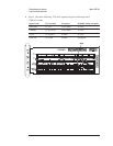
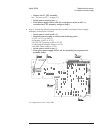
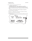
Using a logic probe, check that A7 P7 pin 2 (SCL) and A7 P7 pin 1 (SDA)
toggle TTL states at least twice just after power up.
•
If the signals are not correct, the A7 CPU assembly is probably faulty.
•
If the signals are correct, go to page 4-15, ‘’To troubleshoot power-up
failures.’’
Troubleshooting the Analyzer Agilent 35670A
To perform initial verification
4-10