


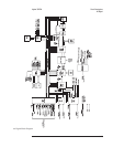

All of these assemblies appear as slaves to the IIC Controller. The IIC Controller has
access to EEPROM, which allows the CPU assembly to store information such as the
analyzer’s serial number. If the CPU assembly is replaced, the EEPROM integrated
circuit (U27) on the faulty assembly must be removed and inserted into the new
assembly (see ‘’What to do before replacing the CPU assembly’’ in chapter 6). The
IIC Controller also has access to a battery backed real-time clock on the A8 Memory
assembly.
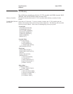
The IIC bus consists of the following four signal lines:
•
SCL (serial clock)
•
SDA (serial data)
•
SINTn (serial interrupt)
•
SINTFPn (serial interrupt for A11 Keyboard Controller assembly)
Pull-up resistors connect these signals to logic high (all four lines are open collector or
open drain). See ‘’A8 Memory,’’ ‘’A11 Keyboard Controller,’’ and ‘’A99
Motherboard’’ in chapter 9 for descriptions of the IIC signals.
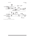
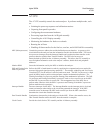
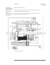
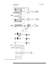
Disk Controller Allows the analyzer to store or retrieve data from the internal 3.5-inch flexible A100 Disk
Drive assembly. It provides all the control signals necessary to operate the Disk Drive
assembly. The Disk Controller performs the following functions:
•
Turns on the disk drive motor
•
Selects the disk drive head
•
Turns on the disk drive LED
•
Selects a track on the flexible disk
•
Writes or reads serial data to or from the flexible disk
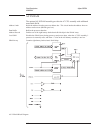
The Disk Controller puts data on the flexible disk in a bit stream that consists of data
and clock bits. When data is read from the disk, this circuit separates the data bits
from the clock bits, converts the serial data bits to an 8-bit parallel word, and puts the
data word on the processor data bus. The operation is reversed when data is written to
the disk.
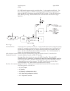
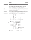
Display Controller Takes parallel data from the processor data bus and places the data in Frame Memory.
Frame Memory
Consists of four 256K 4-bit RAM chips. One bit in Frame Memory corresponds to one pixel
on the display. The data in Frame Memory is then sent to the Video Gate Array.
Video Gate Array Continuously updates the display with the contents of Frame Memory. The Video Gate Array
also supplies the horizontal and vertical sync signals for the display.
RS-232 Interface Allows the analyzer to communicate with other devices such as terminals, plotters, or printers
via Instrument Basic. See Using Instrument Basic with the Agilent 35670A for additional
information.
Agilent 35670A Circuit Descriptions
A7 CPU
8-29