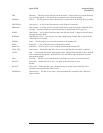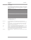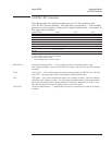
FSELAn Fast Bus Asynchronous Select — This line is low when an asynchronous fast bus cycle is in
operation.
FSELSn Fast Bus Synchronous Select — This line is low when a synchronous fast bus cycle is in
operation. The A6 Digital assembly uses this signal to enable I/O to its gate arrays and to the
A5 Analog assembly’s source attenuator DAC and dc offset DAC.
H10MHZ 10 MHz Clock — This is a 50% duty cycle, 9.961472 MHz clock. This clock is H20MHZ
divided by 2.
H20MHZ 20 MHz Clock — This is a 50% duty cycle, 19.922944 MHz clock. This clock provides the
timing for the analyzer.
HRNGA Half Range A — In both the two channel and four channel analyzer, a high on this line turns on
the channel 1 half range LED. This line goes high when the A1 or A2 Input assembly detects
that the amplitude of the channel 1 input signal reached half the set range.
HRNGB Half Range B — In a two channel analyzer, a high on this line turns on the channel 2 half range
LED. In a four channel analyzer, a high on this line turns on the channel 3 half range LED.
This line goes high when the A1 Input assembly detects that the amplitude of the channel 2
input signal reached half the set range or when the A2 Input assembly detects that the
amplitude of the channel 3 input signal reached half the set range.
HRNGC Half Range C — In a four channel analyzer, a high on this line turns on the channel 2 half
range LED. This line goes high when the A2 Input assembly detects that the amplitude of the
channel 2 input signal reached half the set range. This line is only used in four channel
analyzers.
HRNGD Half Range D — In a four channel analyzer, a high on this line turns on the channel 4 half
range LED. This line goes high when the A2 Input assembly detects that the amplitude of the
channel 4 input signal reached half the set range. This line is only used in four channel
analyzers.
HSYNC Horizontal Synchronization — A high on this line causes the external monitor to do a
horizontal retrace. The Motherboard buffers this signal and routes it to the EXT MONITOR
connector.
IFCn Interface Clear — This line is only used during the analyzer’s development.
IMODE Input Mode — This line indicates the A98 Power Supply assembly’s input power mode. When
this line is high, the Power Supply assembly is operating on ac power. When this line is low,
the Power Supply assembly is operation on dc power.
INTHPIBn GPIB Controller Interrupt — A low on this line interrupts the A7 CPU assembly. This line is
controlled by the A10 Rear Panel assembly’s GPIB controller.
INTONIXn Parallel Port Interrupt — A low on this line interrupts the A7 CPU assembly. This line is
controlled by the A10 Rear Panel assembly’s parallel port controller.
KEYVALID Key Valid — A high on this line interrupts the A7 CPU assembly. This line goes high when a
key is pressed on an external keyboard.
Agilent 35670A Voltages and Signals
A99 Motherboard
9-31


