


For the standard two channel analyzer, do the following to adjust common mode
rejection:
•
Set the power switch to off ( O ).
•
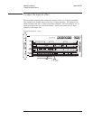
Connect the BNC(f)-to-minigrabber adapter to the BNC cable. Connect
both minigrabber clips (signal and ground) to A5 TP8 and the BNC
connector to the analyzer’s CH 1 connector.
•
Set the power switch to on ( I ).
•
Press the following keys:
[
System Utility ]
[
MORE ]
[
SERVICE TESTS ]
[
ADJUSTMTS ]
[
CHANNEL 1 ADJUSTMNT ]
[
CMRR ]
Wait for the analyzer to set up the adjustment. The analyzer is ready when
the adjustment message appears on the screen.
•
While monitoring the Y: value, adjust A1 R43 for a minimum marker value.
•
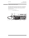
Disconnect the BNC cable from the analyzer’s CH 1 connector and connect
to the CH 2 connector.
•
Press the the following keys:
[
Rtn ]
[
CHANNEL 2 ADJUSTMNT ]
[
CMRR ]
Wait for the analyzer to set up the adjustment. The analyzer is ready when
the adjustment message appears on the screen.
•
While monitoring the Y: value, adjust A1 R543 for a minimum marker
value.
Adjusting the Analyzer Agilent 35670A
To adjust common mode rejection
5-14