


•
Press the following keys:
[
System Utility ]
[
MORE ]
[
SERVICE TESTS ]
[
ADJUSTMTS ]
[ ADC ADJUSTMNT
]
[
OFFSET ]
Wait for the analyzer to set up the adjustment. The analyzer is ready when the
adjustment message appears on the screen.
•
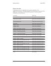
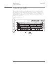
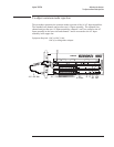
If the oscilloscope display looks like the following figure, go to step 17.
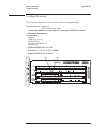
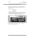
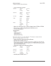
The following describes the signals shown on the oscilloscope display:
‘’
A’’ A straight, horizontal trace in the upper half of the display.
‘’B’’ A “noisy” flat trace at the center of the sine wave trace.
‘’C’’ A clean sine wave in the lower half of the display.
R431 and R405 Correctly Adjusted
•
If trace ‘’B’’ is not flat, adjust A5 R431.
•
If trace ‘’C’’ is not centered over trace ‘’B,’’ adjust A5 R405.
•
Set the power switch to off (
O ).
•
Disconnect the jumper from A5 TP8 and A5 TP300. Reconnect the cable to
A5 P4.
Agilent 35670A Adjusting the Analyzer
To adjust the ADC gain, offset and reference
5-9
A
B
C