


To adjust the ADC gain, offset and reference
This procedure adjusts the second-pass gain, the first-pass offset, and the reference
voltage for the ADC on the A5 Analog assembly. This prevents nonlinear
Analog-to-Digital Converter (ADC) operation near the Digital-to-Analog Converter
(DAC) transition levels.
Equipment Required: Oscilloscope
1:1 Oscilloscope Probe
Capacitive Load
BNC-to-BNC Cable
•
Set the power switch to off (
O ).
•
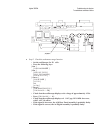
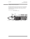
Connect the capacitive load (from the service kit) to the oscilloscope input.
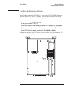
Connect the 1:1 oscilloscope probe to the capacitive load. Attach the probe to
A5 TP400 and the probe ground clip to the instrument chassis.
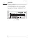
•
Connect the oscilloscope’s external trigger connector to the analyzer’s
SOURCE connector using a BNC cable.
Agilent 35670A Adjusting the Analyzer
To adjust the ADC gain, offset and reference
5-7