


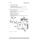
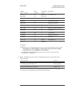
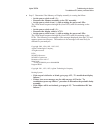

Binary
(DS5) (DS9)
Hexa-
decimal
~Time LEDs
Visible
Description
1111 1111
0000 0000
FF
00
200 ms on
200 ms off
A7 flashes LEDs
0000 1000 08 † starting A7 test
0000 0010 02 † A8 RAM DSACK test
0001 0100 14 † starting A8 RAM test
0001 0110 16 † starting A8 refresh test
0001 1100 1C 4s starting A8 program ROM test
0000 0000 00 4s clear LEDs
1010 0000 A0 † A7 MFP test
1010 0001 A1 † starting A7 DSP test
1010 0010 A2 † fast bus test
0101 1110 AE 200 ms front panel test
1111 1111 FF Remain on
0 = LED off
1 = LED on
† When no failure occurs, these codes appear for only a very short time and probably won’t be visible.
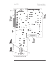
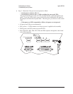
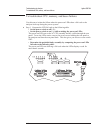
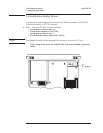
•
If the power-on LEDs display a code for more than 4 seconds, a failure
occurred in the core assemblies or on the buses.
For additional information on the power-on test, see the ‘’Power-on Test
Descriptions’’ on page 10-3.
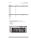
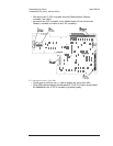
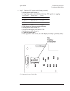
Step 3. Determine the next step by comparing the power-on test results to the
following table.
Power-on LEDs Next Test
LEDs stop and display a fail code.
A7 DS101 (green, run LED) is off.
CPU, memory, and
buses, page 4-18
LEDs pass, but the screen is defective. Display, 4-22
LEDs pass, but it takes more than 3 minutes before the keys are active.
LEDs pass and screen appears normal, but keys do not function.
IIC Bus, page 4-25
Agilent 35670A Troubleshooting the Analyzer
To troubleshoot power-up failures
4-17