


Adjusting the Analyzer
This chapter contains the adjustment procedures for the Agilent 35670A
Dynamic Signal Analyzer. Use these adjustments if the analyzer does not meet
its specifications or if instructed in chapter 4, ‘’Troubleshooting the Analyzer,’’
or chapter 6, ‘’Replacing Assemblies,’’ to perform these adjustments. These
adjustments are not required for routine maintenance.
Allow the Agilent 35670A analyzer to warm up for an hour before doing any of
the adjustments.
During many of these adjustment procedures, an adjustment message appears
on the screen. The instructions on the screen are not as complete as the
instructions in this guide. When an adjustment message appears on the screen,
continue to follow the instructions in this guide. Failure to follow the
instructions in this guide may result in an incorrect adjustment, which would
appear as a hardware failure.
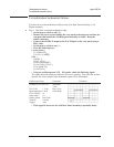
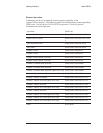
The following table shows the assembly and components adjusted during each
adjustment procedure.
Adjustment Assembly Component
Frequency reference A7 CPU A7 C85
Source A5 Analog A5 R48
A5 R59
ADC gain, offset and
reference
A5 Analog A5 R407
A5 R405
A5 R431
Input dc offset A1/A2 Input A1/A2 R39
A1/A2 R539
Common mode rejection A1/A2 Input A1/A2 R43
A1/A2 R543
Filter flatness A1/A2 Input A1/A2 R115
A1/A2 R235
A1/A2 R615
Display voltage A102 DC-DC Converter A102 R25
5-2