


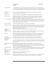
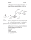
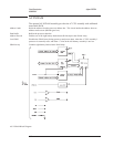

PVALID from the power supply goes high when +5 volts reaches a valid level. The
Reset Generator produces a 128 ms reset pulse when PVALID goes high and S2 is
open, or when S2 is closed then opened and PVALID is high. At the end of the reset
pulse, RSTn goes high, which terminates the reset and allows all circuits to begin
operation.
Reset Logic
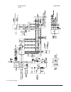
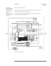
Fast Bus Interface Connects the CPU assembly to the fast bus. All data transfers between the A6 Digital assembly
and the CPU assembly occur over the fast bus. The fast-bus address lines (FA0 through FA5)
and data lines (FD0 through FD15) are simply extensions of the processor address and data
busses. This allows fast transfers between the two assemblies. See ‘’A99 Motherboard’’ in
chapter 9 for a description of the fast bus signals.
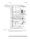
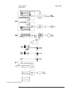
MFP (Multiple-Function
Peripheral) Controller
Handles interrupts and handshaking during data transfers for the IIC Controller, Disk
Controller, Display Controller, and RS-232 Interface.
Interrupts from these circuits are sent to the MFP Controller. When the MFP
Controller receives an interrupt, it interrupts the prioritized Interrupt Handler, which in
turn interrupts the MPU. The MPU then reads a status byte from the MFP Controller
to determine the cause of the interrupt. The MFP Controller also tells the Data
Transfer Handler if any data transfers occurred for these circuits.
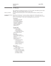
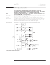
IIC (Inter-IC) Controller Manages the IIC bus. It allows direct communication between the CPU assembly and the
following assemblies via the IIC bus:
•
A1 or A2 Input
•
A5 Analog
•
A8 Memory (calendar/clock chip)
•
A10 Rear Panel (tachometer control)
•
A11 Keyboard Controller
Circuit Descriptions Agilent 35670A
A7 CPU
8-28
81