


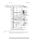
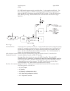


A11 Keyboard Controller
The A11 Keyboard Controller assembly together with the A13 Primary and
A14 Secondary Keypad assemblies make up the front panel keyboard. This assembly
provides the interface between the A7 CPU assembly and the keypads.
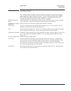
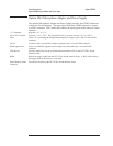
Beeper Generates a tone when instructed by the A7 CPU assembly. The beeper can be turned off by
pressing [ System Utility ][BEEPER ON OFF ].
IIC Controller Decodes data from the IIC bus providing the A13 Primary Keypad assembly with control lines
that turn overload and source LEDs on and off.
Keyboard
Microprocessor
Interrupts the A7 CPU assembly when a key is pressed or the RPG is turned. The CPU
assembly then addresses the Keyboard Microprocessor and reads an 8-bit frame of data from
the IIC bus to determine which key was pressed (for information about the IIC bus, see the
description of the IIC Controller in the ‘’A7 CPU’’ earlier in this chapter).
Interrupt Detection Informs the A7 CPU assembly every time a key is pressed or the RPG is turned.
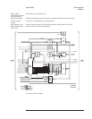
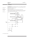
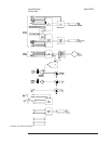
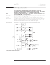
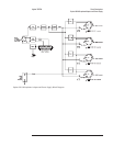
A11 Keyboard Controller Block Diagram
Agilent 35670A Circuit Descriptions
A11 Keyboard Controller
8-35