


•
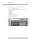
Set the oscilloscope as follows:
Channel 1
Volts/Div
Offset
Coupling
20 mV/div
0V
1M
Ω ac
Channel 2
Volts/Div
Offset
Coupling
500 mV/div
0V
1M
Ω ac
Time Base Time/Div
Sweep
1.0 ms/div
Triggered
Trigger Source
Level
Slope
Mode
Channel 2
500 mV
Positive
Edge
Display Mode
Averaging
No. of Avg.
Screen
Repetitive
On
8
Single
•
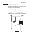
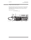
Remove the cable from A5 P4. Connect a jumper from A5 TP8 to A5 TP300.
• Press [
Preset ] while setting the power switch to on ( I ).
• Press the following keys:
[
System Utility ]
[
MORE ]
[
SERVICE TESTS ]
[
ADJUSTMTS ]
[
ADC ADJUSTMNT ]
[
SECOND PASS GAIN ]
Wait for the analyzer to set up the adjustment. The analyzer is ready when the
adjustment message appears on the screen.
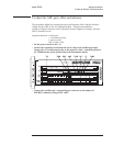
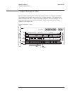
•
Adjust A5 R407 for a flat trace on the oscilloscope.
•
Set the power switch to off (
O ).
•
Disconnect the capacitive load and connect the 1:1 oscilloscope probe directly
to the oscilloscope input. Attach the probe to A5 TP402 and the probe ground
clip to the instrument chassis.
•
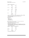
Change the set up for the oscilloscope as follows:
Channel 1
Volts/Div
Coupling
115 mV/div
1M
Ω dc
Channel 2
Coupling
1M
Ω dc
Time Base
Time/Div 500 ms/div
Display Averaging
Display time
off
2.00 s
•
Set the power switch to on ( I ).
Adjusting the Analyzer Agilent 35670A
To adjust the ADC gain, offset and reference
5-8