


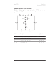

DC Power Cable and Grounding Requirements
The negative side of the dc input connector is not connected to chassis ground.
In dc mode operation, the chassis will float. The chassis ground lug on the rear
panel and the negative side of the dc input connector should both be connected
to a known reference potential.
Two dc power cables are available—the HP 35250A dc power cable and the
HP 35251A dc power cable with cigarette lighter adapter. Both cables contain
a 30 amp, 32 volt fuse (HP 2110-0920).
Warning The tip of the cigarette lighter adapter may get hot during use. After unpluging
the adapter, be careful of the heat from the adapter’s tip.
Caution Although shorter cables may reduce dc voltage loss, use the standard cables. The dc
inrush current may pit the connector contacts in shorter cables.
AC Power Cable and Grounding Requirements
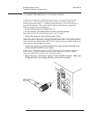
On the GPIB connector, pin 12 and pins 18 through 24 are tied to chassis
ground and the GPIB cable shield. The instrument frame, chassis, and covers
are connected to chassis ground. The input BNCs are floating unless ground
mode is selected.
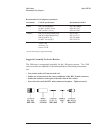
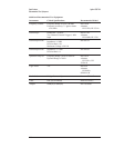
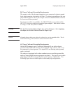
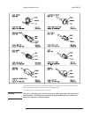
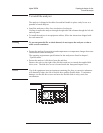
The analyzer is equipped with a three-conductor power cord that grounds the
analyzer when plugged into an appropriate receptacle. The type of power cable
plug shipped with each analyzer depends on the country of destination. The
following figure shows available power cables and plug configurations.
Agilent 35670A Preparing the Analyzer for Use
2-3